
Belt Conveyor Drive Systems · Industrial Gearbox Engineering · Australia
Technical Specifications
The table below summarises the standard engineering parameters engineers specify when selecting a gearbox for belt conveyor drive applications. These ranges cover the majority of light-to-heavy industrial conveyors encountered across Australian operations, from agricultural grain handling to open-cut coal mining.
| Parameter | Typical Range | Notes |
|---|---|---|
| Output Torque | 100 – 250,000 N·m | Heavy quarry duty at upper end |
| Gear Ratio | 5:1 – 100:1 | Single or multi-stage reduction |
| Input Speed | 960 – 1,500 RPM | Matches standard 4-pole / 6-pole motors |
| Output Speed | 15 – 300 RPM | Belt speed range 0.3–5 m/s typical |
| Mechanical Efficiency | 75 % – 98 % | Worm lower; helical-bevel upper |
| Service Factor (SF) | 1.25 – 2.5 | Higher SF for shock-load, dirty environments |
| Mounting | Foot, flange, shaft-mount, hollow bore | Site-dependent; shaft-mount common |
| IP Rating | IP55 – IP67 | Outdoor / dusty agricultural sites need IP66+ |
| Lubrication | Oil bath / forced circulation | ISO VG 220–460 gear oil typical |
| Operating Temperature | −20°C to +80°C ambient | Thermal derating applies above 40°C |
Where Belt Conveyors Need Gearboxes — and Why
A belt conveyor is not a single machine — it is a mechanical system with multiple drive and control points. Each location imposes a distinct loading profile on the gearbox that serves it. Selecting the wrong type for a given position is one of the leading causes of premature drivetrain failure on conveyor installations across Australian mining and agricultural operations. The three critical positions are described below.
Head Drive Station: The Primary Power Point
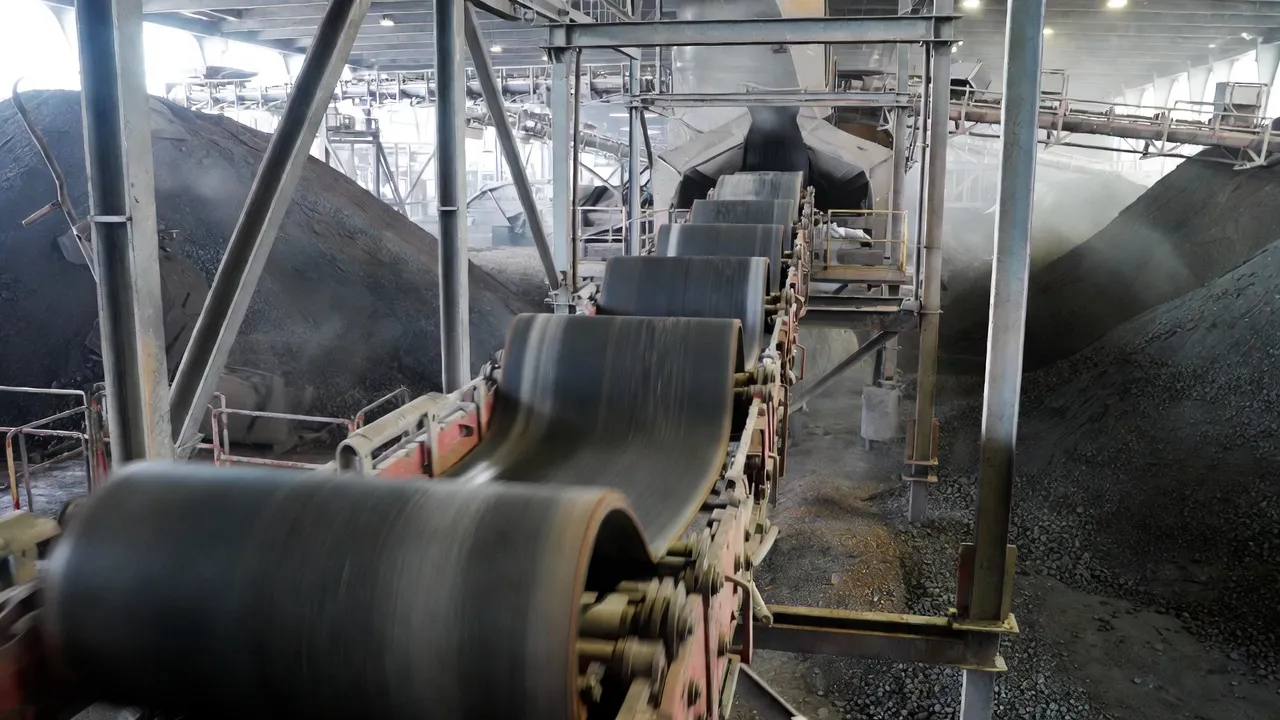
The head drum — located at the discharge end of the conveyor — is where the belt leaves the driven pulley. This is the primary drive station and carries the full tension load of the loaded belt. A robust belt conveyor gearbox mounted at this point must deliver sustained high torque at relatively low output speed. Helical-bevel gearboxes with parallel or right-angle configurations dominate this position on conveyors handling more than 100 tph, because their high mechanical efficiency (94–98%) minimises heat generation during 20-hour continuous shifts common in Australian mining operations. The gearbox is typically coupled directly to a squirrel-cage induction motor via a flexible coupling, with a backstop device integrated to prevent belt rollback on inclined installations.
For shorter agricultural conveyors handling grain, seed, or fertiliser at lower throughputs, a worm gearbox at the head drive provides adequate torque with compact dimensions and built-in self-locking capability — a valuable safety feature that eliminates the need for a separate mechanical backstop. The lower efficiency of worm drives is acceptable at these smaller power levels where energy cost per tonne is less critical.
Tail End and Take-Up Station: Tension Control and Belt Tracking
The tail pulley and take-up assembly require a gearbox only when a powered take-up is specified. Gravity take-ups are passive and need no drive, but in space-constrained installations — particularly underground coal and ore conveyors — an electrically driven winch or screw take-up positions the tail pulley to maintain correct belt tension throughout loading cycles. The gear reducer for this application must hold position under load without drift, making a worm gearbox the preferred selection. Worm drives do not back-drive under typical take-up loads, removing the need for a motor brake and simplifying the electrical control scheme.
Gear ratios for take-up drives typically run 40:1 to 80:1, as travel speed is low and positional accuracy matters more than efficiency. The duty cycle is intermittent — the drive activates only when belt tension deviates from setpoint — so thermal rating is based on on-time fraction rather than continuous power.
Intermediate Drive Points: Booster Drives on Long Conveyors
Belt conveyors exceeding 800 metres in length — common in Australian iron ore, coal, and grain terminals — frequently specify intermediate or booster drive stations along the belt’s run. These intermediate drives share the tension load and reduce peak belt stress, extending belt service life and lowering total installed motor power. Each booster station needs its own gear reducer matched to the same output speed as the head drive, synchronised through variable-frequency drives. Inline helical or helical-bevel units with foot mounting and solid output shafts dominate here, as installation space is usually more generous than at the head station and the emphasis is on high efficiency and low heat generation across long operating periods.
Choosing the Right Gearbox Type for Conveyor Duty
Three gearbox architectures account for the majority of conveyor drive applications. Each suits different conveyor sizes, power levels, and site constraints. Understanding their relative strengths allows engineers to match the mechanical solution to the actual operating demand rather than defaulting to a single type across all positions.
Right-angle drive; compact footprint; self-locking at ratios above 25:1. Efficiency 75–92% depending on ratio. Ideal for take-up drives, agricultural conveyors under 15 kW, and installations where a mechanical backstop would add cost or complexity.
Right-angle drive with helical gear stages for efficiency up to 97%. High torque density, quiet operation, long service life. The go-to selection for conveyor head drives above 22 kW. Available as shaft-mounted (hollow bore) units that eliminate coupling misalignment issues.
Parallel-shaft configuration; highest efficiency of the three (up to 98%); lower radial loads than right-angle types. Suited to horizontal or slightly inclined conveyors where motor and head drum can be arranged in-line. Common in intermediate drive stations on long-haul conveyors.
Gear Ratio Calculation and Output Torque Requirements
Getting the gear ratio wrong is one of the most costly errors in conveyor design. Too low a ratio produces excessive output shaft speed and insufficient torque; too high a ratio wastes motor power and increases drivetrain losses. The correct ratio is calculated from the required belt speed and the head pulley diameter, then cross-referenced against the available motor speed.
Calculating the Required Ratio
The fundamental relationship is straightforward. Belt speed (v, in m/s) equals the head pulley surface speed: v = π × D × n_out / 60, where D is pulley diameter in metres and n_out is pulley speed in RPM. Rearranging for required output speed: n_out = 60v / (π × D). The gear ratio i = n_motor / n_out. For example, a 1-metre diameter head pulley on a conveyor running at 2.5 m/s requires an output speed of 47.7 RPM. With a 1,460 RPM motor, the required ratio is approximately 30.6:1 — pointing toward a two-stage helical-bevel unit or a single-stage worm gearbox depending on power level.
Output Torque and Service Factor
Required output torque is derived from the effective belt pull (F_eff in Newtons) and head pulley radius: T_out = F_eff × r_pulley. The effective belt pull accounts for load weight, inclination resistance, idler friction, and belt flexion losses. In Australian agricultural and mining applications, a minimum service factor of 1.5 is recommended for conveyors with frequent starts and stops or those subject to belt jam events. Heavy mining conveyors handling abrasive ore with impact loading at the feed chute should carry an SF of 2.0 to 2.5 to ensure the gearbox rating comfortably exceeds peak dynamic torque.
Thermal Rating and Duty Cycle
A gearbox with adequate mechanical torque rating can still overheat if the thermal rating is exceeded. Worm gearboxes are particularly sensitive to this on continuous conveyor applications, as their lower efficiency converts a larger fraction of input power to heat. Manufacturers publish thermal ratings as maximum continuously dissipated power; if the calculated heat generation exceeds this figure, forced cooling (cooling fan on the gearbox casing or external oil-to-air heat exchanger) is required. At Australian summer ambient temperatures frequently reaching 38–42°C in open-cut mining environments, thermal derating can reduce the effective gearbox power capacity by 15–25% compared to the rated figure at 20°C — a factor many procurement decisions overlook.
Installation, Mounting Configurations, and Shaft Alignment
Even a correctly sized gearbox fails early if the installation practice is poor. Conveyor drive installations present three specific challenges that differ from general industrial gearbox applications: high radial loads on the output shaft from belt tension, the need for precise angular alignment between gearbox and head pulley shaft, and the requirement for a robust mechanical backstop on inclined runs.
Maintenance Strategies to Extend Belt Conveyor Gearbox Life
A correctly specified gear reducer for belt conveyor applications should run for 60,000 hours or more between overhauls if maintained properly. In practice, gearbox failures on Australian conveyor installations overwhelmingly trace back to three root causes: contaminated oil, incorrect lubricant viscosity, and inadequate bearing preload after thermal cycling. A structured maintenance programme addresses all three.
Oil Analysis and Change Intervals
Oil analysis is the single most valuable diagnostic tool for conveyor drive gearboxes. A sample taken every 1,000 operating hours and analysed for viscosity, ferrous particle count, water content, and acid number reveals developing problems months before they produce audible symptoms. In the mining industry, oil analysis is standard practice; in agricultural operations running grain conveyors, it is less common but equally valuable. The first oil change after a new gearbox installation should occur at 500 hours to flush break-in wear particles. Subsequently, ISO VG 220 mineral oil suits most worm drives while ISO VG 320 or 460 is more appropriate for heavily loaded helical-bevel units in summer temperatures.
Seal Integrity and Contamination Control
Conveyor environments are inherently dusty. Grain elevators, coal handling terminals, and mineral processing plants generate fine particulate that infiltrates lip seals through shaft movement and pressure fluctuations. Upgrading shaft seals from single-lip to double-lip configurations, or adding an external labyrinth seal cover, extends seal service life significantly. Gearboxes mounted near belt scrapers or water spray cleaning systems are particularly vulnerable to water ingress — IP66 rated sealing should be specified as a minimum in washdown environments, with a breather valve vented away from direct water impingement.
Vibration Monitoring and Bearing Condition
Installing a vibration sensor on the gearbox casing — either permanently wired to a plant SCADA system or fitted with a Bluetooth-enabled transmitter for periodic route-based monitoring — allows trending of bearing defect frequencies before catastrophic failure. For conveyors with downtime costs above $5,000 per hour (a realistic figure for many Australian mining operations), the capital cost of continuous vibration monitoring is recovered within a single avoided breakdown event. Alert thresholds should be set conservatively at 150% of the baseline RMS velocity; alarm levels at 250% of baseline trigger immediate inspection rather than waiting for the next scheduled service.
Belt Conveyor Gearbox Applications Across Australian Industries
Australia’s industrial geography creates conveyor challenges found in few other countries: extreme ambient temperatures in Western Australia and Queensland, long transport distances that favour very long conveyors over truck haulage, and a diverse mix of bulk materials spanning mineral ore, agricultural grain, and processed food products. Each sector places distinct demands on the gearbox at the conveyor’s heart.
Variable Frequency Drives and Soft-Start Integration
Starting a loaded belt conveyor directly on-line subjects the drivetrain to starting torque spikes of 5–8× the rated full-load torque. At a 500-tonne sand and gravel conveyor, this translates to tens of thousands of Newton-metres of instantaneous torque that fatigues gear tooth flanks, stresses coupling elements, and can shear soft key connections. Two technologies address this: soft starters and variable-frequency drives (VFDs).
A soft starter limits the starting current and progressively ramps the motor voltage, reducing starting torque to roughly 1.5–2× rated. This is adequate for most level conveyors but cannot provide the low-speed torque needed for tensioning long inclined belts on startup. A VFD applies full motor flux from zero speed, delivering rated torque throughout the acceleration ramp — essential for inclined mining conveyors or those restarting under full load. When a VFD is specified, the gearbox must be rated for the motor’s maximum torque output at any frequency in the operating range, since VFDs can command torques significantly above the nameplate motor rating during acceleration.
It is worth noting that worm gearboxes paired with VFDs require careful attention to minimum speed limits. Below approximately 300 RPM input speed, forced lubrication or careful oil bath level management prevents inadequate bronze wheel lubrication at the meshing zone — a failure mode that shortens worm wheel life substantially and is the primary reason helical-bevel units are preferred for variable-speed conveyor head drives above 15 kW.
Sourcing and Specifying Gearboxes for Australian Conveyor Projects
Australian conveyor projects carry procurement challenges that differ from European or North American equivalents: lead times from offshore manufacturers of 10–16 weeks, customs and import duty considerations, and limited local inventory for large industrial gearbox units. A practical sourcing strategy combines a technically precise specification with a supplier capable of local technical support.
The specification document should always state: rated output torque (not just motor power), required gear ratio, input speed, mounting configuration (foot or shaft-mount), service factor, ambient temperature range, IP rating, and any special requirements such as food-grade lubricant, stainless shaft extension, or integrated backstop provision. Providing these parameters upfront eliminates the back-and-forth clarification cycle that extends procurement timelines on tight project schedules.
For conveyor drives requiring bevel gear stages — common in right-angle head drives and cross-conveyor transfer points — the geometry of the bevel mesh is as critical as the ratio. Sourcing from a supplier specialising in precision bevel gears for industrial applications ensures the tooth profile and flank correction are validated for continuous conveyor loading rather than the lighter intermittent duty for which some commercial bevel units are designed.
If you are designing a new conveyor system or replacing an existing drivetrain, our team can assist with ratio verification, mounting configuration selection, and lead-time planning. Explore the full range of worm gearbox and helical-bevel conveyor drive solutions available for Australian operations, or reach out directly through our contact our engineering team page for a project-specific recommendation.
Common Gearbox Selection Mistakes on Conveyor Projects
Years of field experience with Australian conveyor installations reveal a consistent set of specification and procurement errors. Recognising these patterns before they become field failures saves both capital and production time.
Motor power expressed in kilowatts tells you input energy; it says nothing directly about output shaft torque, which is what the belt tension imposes on the gearbox. A 22 kW motor driving through a 30:1 ratio produces approximately 4,300 N·m of output torque. Size the gearbox to the torque figure, not the power rating, to avoid selecting an underrated unit that appears adequate on paper.
Gearbox thermal ratings assume 20–25°C ambient. At 42°C in an outback Queensland mining operation, thermal power capacity can drop 20–30%. Specifying a unit without applying the manufacturer’s thermal derating factor, or without adding a cooling fan, results in a gearbox that runs hot and burns through oil viscosity class within months. Always apply ambient temperature correction and confirm oil change intervals suit the actual site temperature profile.
A direct-on-line start subjects a gearbox to shock torque that can be 5–8× the running torque. Applying an SF of 1.0 or 1.1 (common when selecting on power alone) leaves no margin for these transients. On conveyors starting under full load or those subject to belt jam events, a minimum SF of 1.5–2.0 is required to prevent tooth flank fatigue and key shear over a reasonable service life.
Concrete grouting shrinks as it cures, shifting the motor and gearbox baseframe by 0.1–0.3 mm. A laser alignment check after final grout cure — before first start — is not optional. Misalignment introduces cyclic bending moments on the output shaft that can cause fatigue cracking of the shaft shoulder within the first 2,000 operating hours, well within the warranty period but easily attributable to installation error.
Frequently Asked Questions
Practical answers to the questions most commonly raised by engineers, maintenance supervisors, and procurement managers working on Australian conveyor projects.