
Feeder & Sorter Drive Systems · Industrial Gearbox Engineering · Australia

Technical Specifications
Key engineering parameters for gearboxes used in feeder and sorter applications, where flow rate accuracy and actuation repeatability are the primary performance metrics alongside the standard torque and ratio requirements.
| Parameter | Typical Range | Notes |
|---|---|---|
| Output Torque | 2 – 10,000 N·m | Precision dosing screws to bulk belt feeders |
| Speed Stability | ±0.1 – ±2% of set speed | Tighter for gravimetric and pharmaceutical feeders |
| Backlash (sorters) | <5 arc-minutes | Timing accuracy of divert actuators |
| Actuation Speed | 50 – 300 ms per divert cycle | High-speed sorters at lower end |
| Service Factor | 1.5 – 2.5 | Higher for lump-prone or abrasive feeder materials |
| Duty Cycle | Continuous to high-frequency intermittent | RMS torque governs sorter gearbox sizing |
Feeder Equipment: Flow Rate, Accuracy, and Drive Demands
Feeders regulate the flow rate of bulk material — powder, granules, aggregate, food ingredients, or chemical products — from a storage hopper into a process, filling line, or transport system. The gearbox in a feeder application does not just provide torque and speed; it must deliver a specific, consistent speed that directly determines the material flow rate, and this speed must be controllable across a wide range without instability.
Screw Feeders: The Most Common Feeder Type
A screw feeder uses a rotating helical screw in a trough or tube to move a controlled volume of material per revolution from the hopper outlet to the process inlet. The gearbox output shaft speed directly determines the volumetric delivery rate: feed rate (m³/min) = screw cross-sectional area × pitch × RPM × fill factor. This linear relationship between speed and flow rate makes screw feeders highly amenable to VFD flow rate control — the controller adjusts gearbox input frequency to set the desired feed rate, with feedback from a weigh belt or flow meter for gravimetric accuracy.
The gearbox must maintain constant speed under variable material resistance — a screw feeder handling powder that sometimes bridges, clumps, or packs against the screw flight will experience sudden load variations that the gearbox must absorb without speed perturbation. A worm gearbox with inherent non-back-drivability resists the tendency of material pressure to slow or reverse the screw; the self-locking characteristic keeps the screw at the commanded speed even under momentary load spikes from bridged material breaking away from the hopper wall. For continuous-duty industrial screw feeders above 5 kW, helical-bevel gear motors with lower heat generation are preferred over worm types, particularly in warm Australian environments.
Service factor selection for screw feeder gearboxes follows material type. For dry, free-flowing powders and granules: SF 1.5. For cohesive, sticky, or moisture-sensitive materials that can bridge and release: SF 2.0. For abrasive materials (sand, mineral concentrate, cement) where jam events produce torque spikes: SF 2.5. The starting torque when the feeder restarts against a packed or bridged material head is the most demanding condition — a feeder that regularly restarts against full head pressure requires a SF at the upper end of the range regardless of the steady-state running torque.
Belt Feeders and Apron Feeders
Belt feeders and apron feeders use a moving belt or steel-plate apron beneath a hopper opening to control material draw-down rate. The feeder belt speed — and therefore the extraction rate — is set by the gearbox output speed via a head pulley drive. These are typically larger, higher-power applications than screw feeders: a belt feeder under a ROM ore bin may be 30–150 kW. The gearbox must handle the high starting torque of lifting the material column above the belt off its static rest, which for a deep-bin high-density ore feeder can reach 3–4× the running torque. Helical-bevel or epicyclic reducers with integrated backstop are the standard for large belt feeder drives in Australian mining.
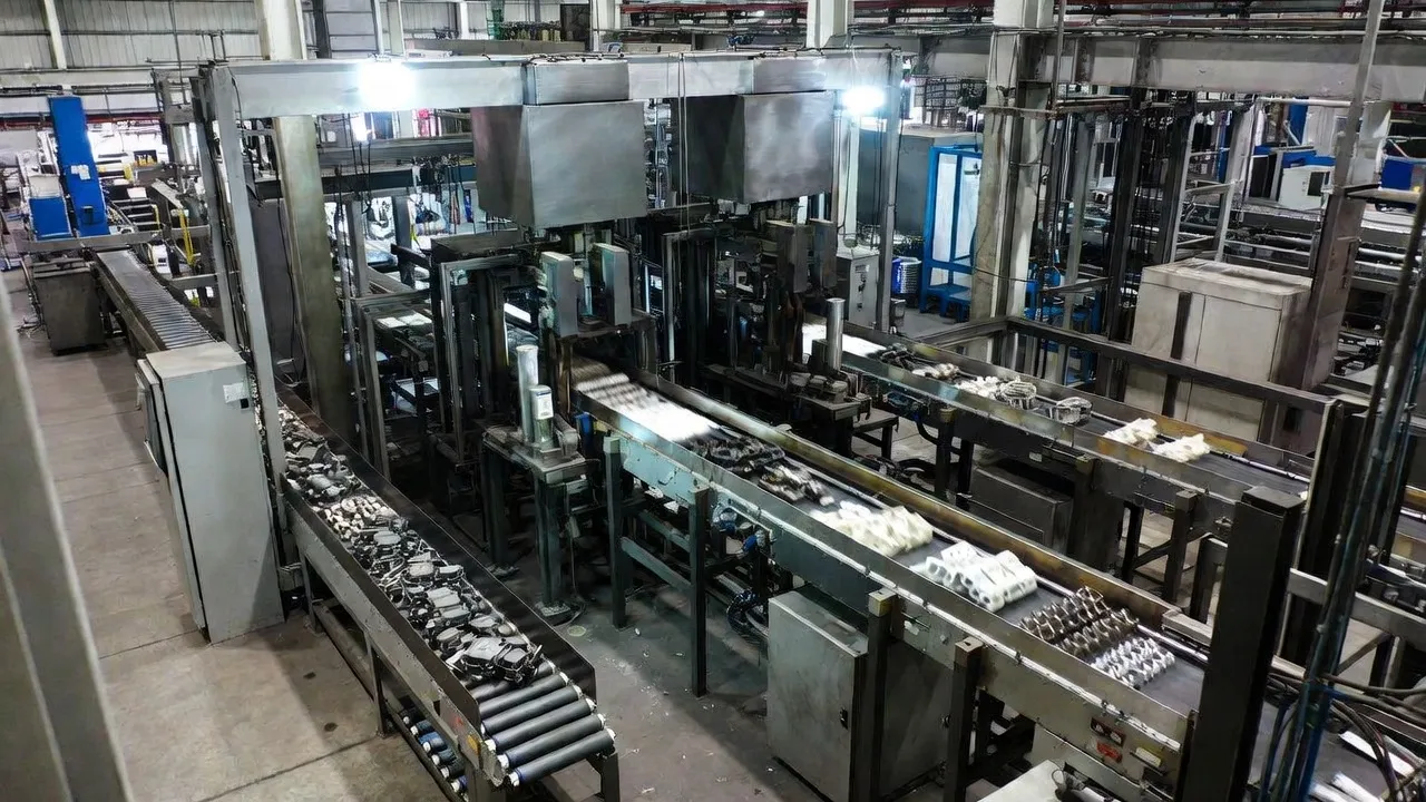
Sorter Equipment: Actuation Speed, Cycle Count, and Timing Accuracy
Sorters route items from a main conveyor line to one of several destination lanes — in an e-commerce fulfilment centre, this might be 50 destinations from a single sortation loop; in a parcel delivery depot, 200 chutes from a cross-belt sorter. The gearbox in a sorter divert mechanism must actuate within a precise timing window — typically 50–300 milliseconds — and then return to the home position ready for the next item in the stream.
Pop-Up Divert Sorters
Pop-up divert sorters lift a driven wheel or belt section above the main conveyor surface to redirect the item laterally to a side lane. The divert mechanism is driven by a small gear motor — typically 0.1–0.4 kW — that must execute the lift cycle in under 150 ms, complete the item transfer, and return within the gap between successive items on the main conveyor. The gearbox must provide the angular precision to stop the pop-up at exactly the lift height — too low and the item drags; too high and the transition is rough. Low backlash (below 5 arc-minutes) and fast actuation speed, combined with a reliable position-hold at the lifted position, define the gearbox requirements for pop-up sorter applications.
Cross-Belt Sorter Carriers
Cross-belt sorters carry items on individual carrier carts, each equipped with a small belt driven by an on-board gear motor. The gearbox drives the carrier belt at exactly the right speed to slide the item off the carrier at the correct divert chute, matched to the timing of the main sorter loop speed. Each carrier’s gear motor must be identical in ratio and output speed to maintain sortation timing accuracy across the entire carrier population. Precision planetary gear motors with confirmed output speed variance below ±1% across a production batch are the correct specification for cross-belt sorter carrier drives, where even a small speed variation between carriers causes items to overshoot or undershoot their destination chutes in the timing-based sortation logic.
RMS Torque Sizing for High-Cycle Sorter Drives
Sorter divert mechanisms operate at cycle rates of 20–200 actuations per minute at peak throughput. This intermittent-duty profile means the gearbox thermal load is determined by the RMS torque over the duty cycle, not the peak actuation torque.
RMS torque = √[(T²₁×t₁ + T²₂×t₂ + T²₃×t₃) / (t₁+t₂+t₃+t_dwell)], where T₁, t₁ are the acceleration torque and duration; T₂, t₂ are the constant-speed torque and duration; T₃, t₃ are the deceleration torque and duration; and t_dwell is the idle time between actuations. For a pop-up divert with 150 ms actuation cycle and 800 ms dwell at 100 actuations per minute: the dwell period significantly reduces the RMS torque below the acceleration peak. However, at 200 actuations per minute with only 150 ms dwell, the RMS torque approaches the peak acceleration torque and the gearbox must be thermally rated for near-continuous duty. Confirm the RMS torque against the gearbox continuous thermal torque rating for each sortation throughput level before selection.
Additionally, bearing fatigue life at high cycle rates must be confirmed. A sorter divert gear motor performing 200 actuations per minute × 60 minutes × 16 hours × 365 days = 70 million reversals per year. Bearing L10 life calculated at the RMS radial load and this cycle frequency should exceed the intended service interval — typically 5–10 years for a sorter installation — before the gear motor selection is finalised.
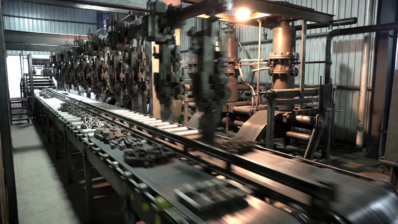
Feeder and Sorter Applications Across Australian Industries
Sourcing Feeder and Sorter Gearboxes in Australia
Feeder gearbox specifications must state: required output speed range (minimum and maximum RPM for VFD-controlled feeders); speed stability requirement (% variation at set speed under variable load); output torque at the starting condition and steady-state service factor; IP rating and any food-grade or pharmaceutical construction requirements; ambient temperature range; and for gravimetric feeders, confirmation that the gearbox does not generate periodic speed variation at frequencies that would interfere with the weigh cell measurement system. For sorter divert gear motors, add the RMS torque at maximum cycle rate, backlash maximum, actuation cycle time, and bearing fatigue life confirmation at the maximum cycle frequency. For shaft-coupled feeder drives where the coupling dimensions must match existing conveyor shafting, providing accurate shaft coupling dimensional data prevents the misalignment issues that cause premature screw feeder gearbox failure.
We supply worm gearboxes, helical-bevel gear motors, and precision planetary units for feeder and sorter applications across Australia. Browse configurations on our feeder and sorter drive solutions page, or contact our engineering team with your material type, flow rate, cycle rate, and accuracy requirements for a specification within one business day.
Frequently Asked Questions
Common questions from process engineers and systems integrators specifying gearboxes for feeder and sorter applications.