Energy & Environmental Equipment Drive Systems · Industrial Gearbox Engineering · Australia
Technical Application Reference
Australia’s energy transition and expanding environmental compliance requirements are driving sustained demand for reliable gearboxes across wind, solar, waste management, and water treatment equipment. These applications share a demanding set of characteristics: outdoor exposure, often-remote installation, variable load profiles from renewable energy sources, and a regulatory expectation of long service life with minimal unplanned maintenance. This guide covers the key gearbox applications in energy and environmental equipment, selection criteria specific to these sectors, and Australian industry context.
Wind, Solar & Hydro Drives
Waste Management & Water Treatment
Renewable Energy & Environmental Compliance

Technical Specifications
Key parameters for gearboxes deployed in energy generation and environmental equipment, from compact solar tracker drives to heavy-duty waste processing shredder gearboxes.
| Parameter |
Typical Range |
Notes |
| Output Torque |
100 – 500,000 N·m |
Solar tracker drive to wind yaw gearbox |
| Gear Ratio |
10:1 – 1,000:1 |
High ratios for slow solar/yaw positioning |
| Duty Cycle |
Intermittent to 24/7 continuous |
Waste processing and water treatment 24/7 |
| Service Factor |
1.5 – 3.0 |
Waste shredders and compactors at upper end |
| IP Rating |
IP55 – IP66 |
Outdoor renewable and waste handling sites |
| Design Life |
20–25 years |
Renewable energy projects matched to asset life |
Wind Energy: Yaw, Pitch, and Generator Drives
Wind turbines represent the most engineering-demanding gearbox application in the energy sector. The nacelle sits atop a 60–120 metre tower exposed to the full wind load, and the gearbox must function reliably for 20 years with only scheduled maintenance access at intervals typically dictated by crane availability — a significant logistical constraint, particularly at the remote wind farm sites typical of South Australia, Victoria, and Western Australia.
Yaw Drive Gearboxes
The yaw system rotates the entire nacelle around the tower axis to keep the rotor facing into the wind. Multiple yaw gearboxes — typically 4–8 units per turbine — drive pinions meshing with a large internal yaw ring gear. Each yaw gearbox must produce high output torque at very low speed (the nacelle turns at approximately 0.5–1° per second), requiring gear ratios in the range of 500:1–2,000:1. Self-locking at rest is essential to hold nacelle position against wind gusts without brake power. Multi-stage helical-planetary combinations or worm-planetary hybrids deliver the required ratios in a compact nacelle-mountable housing.
Pitch Drive Gearboxes
The pitch system adjusts each rotor blade angle to control turbine power output and provide emergency stop capability. Individual blade pitch gearboxes must respond rapidly to control commands and withstand the cyclic aerodynamic and centrifugal forces transmitted through the blade root bearing. Planetary gearboxes with emergency backup power (battery or capacitor) ensure pitch can drive blades to feathered position during grid loss — the critical fail-safe function that prevents overspeed. Pitch gearboxes operate in the hub, which experiences the highest vibration and fatigue loading of any turbine component, making bearing selection and fatigue rating at least as critical as torque rating.
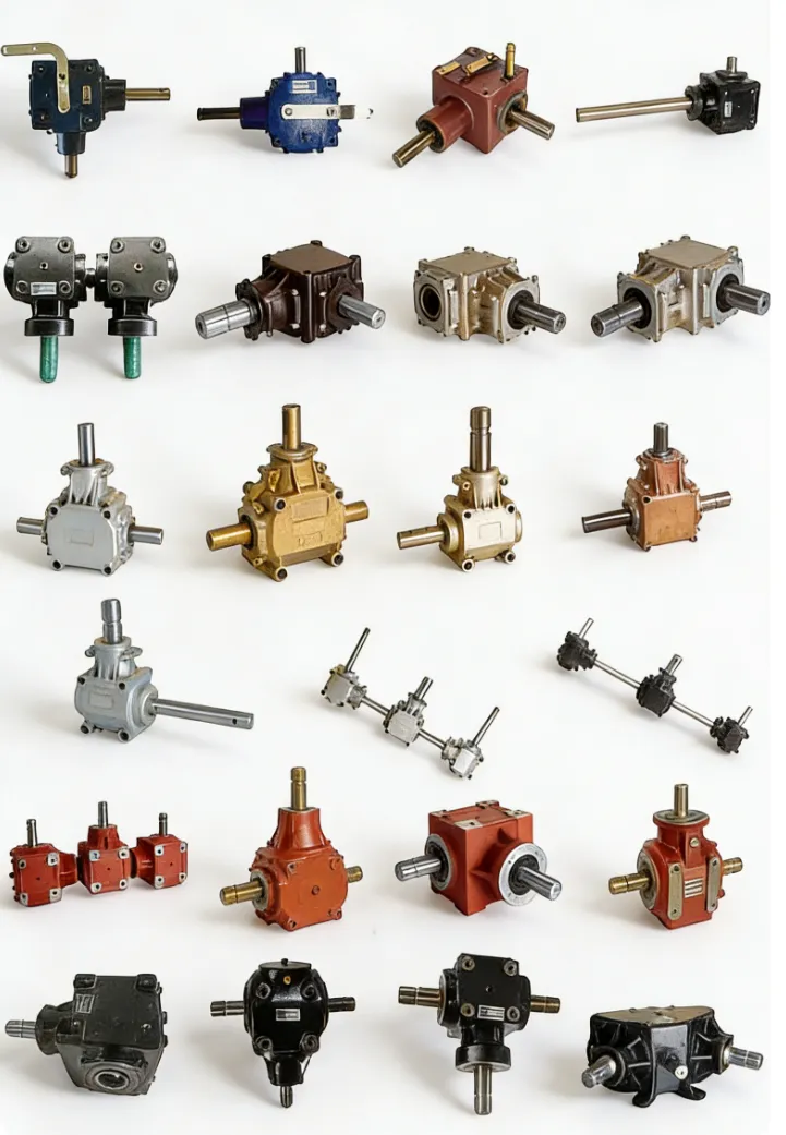
Solar Energy: Tracker and Concentrator Drives
Solar tracker systems improve energy yield by 15–25% over fixed-tilt panels by continuously orienting the solar array toward the sun. Single-axis trackers rotate on a north-south horizontal axis; dual-axis trackers additionally adjust tilt. Both require a drive gearbox at each tracker row actuator providing precise, slow positioning under intermittent duty — the actuator moves the array slowly during daylight hours and returns to home position at dawn.
The gearbox specification for solar tracker drives must address three non-obvious requirements. First, the system must hold position against wind loading without drawing continuous motor power — worm gearboxes at ratios above 40:1 provide self-locking that holds the panel array in position between adjustment commands without the motor remaining energised. Second, because large utility-scale solar farms may have hundreds or thousands of individual tracker drives, standardisation on a single compact gearbox model is essential for spare parts management over a 25-year farm life. Third, the gearbox must survive Australian temperature extremes — from −5°C winter nights in SA and VIC to +55°C surface temperatures in summer — without seal or lubricant failure, which points firmly to synthetic oil from commissioning rather than mineral oil.
Environmental Equipment: Waste Processing and Water Treatment
Waste Shredders & Compactors
Municipal solid waste shredders, industrial waste processors, tyre recycling shredders, and baling press drives impose the most severe shock loading in environmental equipment. Rotor jams from unpredictable waste streams, reverse torque from unjamming sequences, and peak torques of 3–5× running torque at every jam event demand SF 2.5–3.0 and a torque limiter to protect the gearbox. Helical-bevel units with hollow bore shaft mounting and integrated backstop are the standard for shredder drives above 30 kW.
SF 2.5–3.0 · Shock loads · Torque limiter required
Wastewater Treatment Drives
Thickener rakes, clarifier drives, aeration pond agitators, and sludge screw conveyor drives at Australian water utilities run continuously at low speed under sustained torque. Helical-bevel agitator drives with remote monitoring are standard for larger installations; worm gearboxes serve smaller ponds and secondary treatment agitators. Drives operate outdoors in all weather conditions — IP65 minimum, synthetic oil, and desiccant breather are the baseline specification for outdoor water treatment equipment.
24/7 continuous · Outdoor · IP65 + synthetic oil
Biogas & Biomass Plant Drives
Anaerobic digestion plants at Australian agricultural and municipal sites use slow-speed agitator gearboxes for digester mixing, screw conveyors for feedstock handling, and pump drives for gas-to-grid compression. The biogas atmosphere requires ATEX Zone 1 or Zone 2 classification for all electrical equipment. Gearbox external surfaces must not exceed the temperature class limit for the specific biogas composition (typically T3 or T4, corresponding to 200°C or 135°C surface temperature limits).
ATEX Zone 1/2 · Biogas atmosphere · Temperature class rated
Australian Energy and Environmental Industry Applications

Wind Farm Development (SA, VIC, WA)
South Australia leads Australia in wind penetration; Victoria and Western Australia are expanding rapidly. Wind farm operators specify yaw and pitch gearboxes from certified OEM-approved suppliers and maintain component availability programmes for the 20-25 year turbine design life. Aftermarket yaw gearbox replacements are a growing service segment as first-generation Australian wind farms approach 15-20 years of operation.
Utility-Scale Solar (QLD, NSW, SA)
Queensland, NSW, and SA host Australia’s largest utility-scale solar farms, many incorporating single-axis tracking. Each tracker row requires a compact, self-locking worm or planetary gearbox that can tolerate high ambient temperatures and 25-year field life with minimal service access. Volume procurement for large solar farms creates the opportunity for significant standardisation and unit cost reduction compared to bespoke specification.
Waste Management & Recycling
Australia’s landfill diversion targets and expanded recycling infrastructure investment are driving demand for reliable shredder, baler, and compactor drives. The Chinese-origin waste export ban has accelerated domestic processing capacity investment. Helical-bevel shredder drives with integrated backstop and torque limiter are the standard mechanical protection package for new waste processing facilities.
Water Utilities & Treatment Plants
Australian state water utilities operate hundreds of water treatment and wastewater treatment plants requiring reliable, long-service drive equipment for clarifiers, aeration agitators, sludge handling screws, and pump drives. Remote monitoring is increasingly specified for drives at unmanned or partially staffed treatment facilities, enabling the transition from time-based to condition-based maintenance programmes.

Sourcing and Specifying Energy and Environmental Gearboxes
Energy and environmental gearbox specifications share one consistent requirement not found in most industrial applications: a design life that matches the project asset life — 20–25 years for renewable energy, 30+ years for water infrastructure. This drives conservative service factor selection, synthetic lubrication, and remote condition monitoring as baseline rather than premium options. For renewable energy projects where PV shaft connections between trackers and their structural framework must be accurately specified, drive shaft dimensional and tolerance data should be confirmed before ordering gearbox bore dimensions to ensure a fit that requires no field machining.
We supply worm gearboxes, helical-bevel units, and gear motors for energy and environmental equipment across Australia. Browse configurations on our worm gearbox and energy equipment drive solutions page, or contact our engineering team for a specification recommendation within one business day.
Frequently Asked Questions
Common questions from project engineers, asset managers, and procurement teams working on energy and environmental equipment in Australia.
1. Why is a worm gearbox preferred for solar tracker drives?
+
Worm gearboxes suit solar tracker drives for three specific reasons. First, the self-locking characteristic at ratios above 40:1 holds the solar panel array in its commanded position against wind loads without requiring the motor to remain energised — critical for both energy efficiency (the motor only draws power during adjustment moves) and failsafe security (a power interruption leaves the array held in its last position rather than free to rotate in the wind). Second, single-stage ratios of 40:1–100:1 cover all tracker azimuth and elevation speed requirements in one compact unit. Third, the compact right-angle form factor simplifies structural integration into tracker framework designs. The trade-off — lower efficiency than planetary alternatives — is acceptable for the intermittent duty of a solar tracker that moves slowly for a few hours per day.
2. What gear ratio range is typical for a wind turbine yaw drive?
+
Wind turbine yaw gearboxes typically produce overall gear ratios of 500:1–2,000:1 from a standard 1,450 RPM induction motor to a pinion output of approximately 0.7–3 RPM. The pinion meshes with the yaw ring gear on the tower top flange, producing a nacelle rotation speed of approximately 0.3–1° per second. High ratio in a compact nacelle-mountable form factor drives multi-stage helical-planetary combinations or worm-planetary hybrid designs. Each turbine uses multiple yaw gearboxes operating in synchrony — typically 4–8 units — to distribute the yaw ring tangential load around the circumference rather than concentrating it on two or three pinions.
3. What service factor should I specify for a waste shredder gearbox?
+
Waste shredder gearboxes should be specified at SF 2.5–3.0. The load profile of a shredder is inherently non-uniform — normal running torque interrupted by repeated jam events where the rotor contacts an unshredable object and torque spikes to 3–5× the running value before the torque limiter or overload relay trips. The gearbox must survive these events without tooth fracture even when the torque limiter response is slightly delayed. Additionally, a mechanically integrated torque limiter set at 200–250% of rated motor torque protects the gearbox independently of the electrical overload — the combination of SF 3.0 gearbox rating and torque limiter protection provides a system that can survive realistic operating conditions over the 20+ year design life of a waste processing facility.
4. How do I specify a gearbox oil life of 20+ years for a solar tracker?
+
No gear oil lasts 20 years in service without monitoring or change — the specification challenge is to maximise change intervals while maintaining adequate lubrication quality. For solar tracker worm gearboxes with intermittent duty in sealed IP65+ housings in a clean environment: full-synthetic ISO VG 220 worm gear oil provides change intervals of 20,000–30,000 hours under normal operating conditions, equivalent to 10–15 years. For a 25-year solar farm, plan one oil change at year 12–15 coinciding with scheduled structural inspection of the tracker framework. Desiccant breathers prevent water accumulation between changes. Specify the gearbox with a sealed housing and no field-refillable oil level plug to reduce contamination risk during oil changes in a dusty outdoor environment.
5. What ATEX requirements apply to gearboxes in biogas plants?
+
Biogas (primarily methane, Group IIA) is Zone 1 (explosive atmosphere likely during normal operation) near the digester, gas collection, and gas handling areas, and Zone 2 (explosive atmosphere unlikely but possible) in surrounding areas. All electrical equipment — motors, sensors, cable glands — must be certified Ex IIA T3 or better for Zone 1. The mechanical gearbox itself does not require ATEX certification but its surface temperature under overload must be confirmed below the biogas group IIA auto-ignition temperature (537°C for methane — easily met by any normally operating gearbox). The more practically constraining temperature class limit is for biogas from agricultural waste which may contain hydrogen (Group IIB) — confirm the specific gas group with the biogas composition analysis before finalising ATEX equipment group selection.
6. What remote monitoring approach is most practical for water utility gearboxes?
+
For water utility gearboxes at partially staffed or unmanned treatment facilities, the most practical remote monitoring approach combines a wireless vibration and temperature sensor mounted on the gearbox casing with transmission to the site SCADA system via the existing plant telemetry infrastructure. Alarm thresholds set at 150% of the baseline vibration RMS and 10°C above the normal operating temperature differential provide early warning of developing bearing defects and thermal issues, typically 4–8 weeks before failure symptoms become audible. The sensor should be installed at commissioning when scaffold or access equipment is in place — retrofitting to an operating gearbox above a 6-metre clarifier requires a work-at-heights permit and significantly more time and cost than fitting it during the initial installation.
7. What documentation should an energy sector gearbox include for project handover?
+
For energy project handover documentation, the gearbox package should include: dimensional drawings; rated output torque, gear ratio, and efficiency at rated load; thermal power rating at site ambient temperature; oil type, grade, and fill volume; bearing part numbers for all main shafts; IOM manual with oil change procedure and interval; ATEX certificate for motor and electrical accessories if applicable; IP test certificate; design life calculation or confirmed L10 bearing life at rated load; and lubricant SDS. For renewable energy projects with 20+ year operational commitments, the supplier should also confirm parts availability commitment and service network coverage — a gearbox requiring a proprietary bearing that goes out of production at year 12 creates an avoidable replacement cost.
8. Can the same gearbox model be used for both fixed and tracking solar installations?
+
Fixed-tilt installations do not have drive gearboxes — the support structure is bolted in position at the design tilt angle. Tracking systems require the worm or planetary actuator gearbox. Within tracking systems, single-axis trackers are the overwhelming majority for utility-scale solar and use a single gearbox per tracker row on the main drive actuator. Dual-axis trackers add a second gearbox for elevation adjustment. For a project with a mix of single-axis and dual-axis trackers, the same worm gearbox model can serve both applications if the ratio and output torque are matched to the higher-demand dual-axis application — the single-axis application will be slightly oversized, which is not a problem for a self-locking worm drive where the position-holding function dominates the specification rather than running efficiency.
Get the Right Gearbox for Your Energy or Environmental Project
Share your application type, output torque, duty cycle, ambient temperature range, and design life requirement — our engineers will return a complete specification within one business day.
Request a Free Energy Equipment Specification →
