Lifting & Hoisting Drive Systems · Industrial Gearbox Engineering · Australia
Technical Application Reference
Lifting and hoisting equipment places the most demanding and safety-critical loads an industrial gearbox will encounter. A hoist gearbox failure does not just stop production — it risks structural damage, injury, and regulatory consequences. Selecting the correct type, ratio, service factor, and duty class is therefore not optional engineering conservatism; it is the baseline requirement. This guide covers the engineering case for lifting and hoisting gearboxes across Australian industrial operations.
FEM/ISO Duty Class Rated
Hoist, Crane & Winch Drives
Mining, Construction & Port Applications
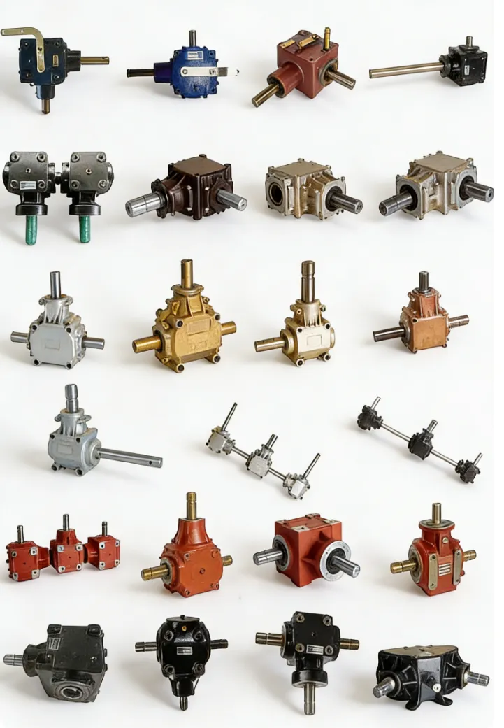
Technical Specifications
Key engineering parameters for gearboxes applied in lifting and hoisting equipment, from light workshop hoists to heavy overhead cranes and mine winding gear.
| Parameter |
Typical Range |
Notes |
| Output Torque |
100 – 500,000 N·m |
Workshop hoist to heavy mine winder |
| Gear Ratio |
8:1 – 200:1 |
High ratios for slow-speed heavy lifts |
| Drum / Hook Speed |
1 – 30 m/min (hoist) |
AS 1418 class defines duty and speed |
| Service Factor |
2.0 – 4.0 (FEM M5–M8) |
Higher than any other application category |
| Holding Brake |
Motor or gearbox mounted |
Mandatory; rated for 150% of hoist load torque |
| Mounting |
Foot, flange, direct drum coupling |
Direct-coupled drum most common in hoists |
| Regulatory Standard |
AS 1418, FEM, ISO 4301 |
Must be stated on documentation for Australian sites |
Where Lifting Equipment Needs Gearboxes
Lifting and hoisting equipment encompasses electric chain hoists, wire rope hoists, overhead cranes, jib cranes, aerial work platforms, mine winders, and marine deck winches. Each applies a unique combination of load, duty cycle, and safety requirements to the drive gearbox.
Electric Hoists and Overhead Cranes
Electric wire rope and chain hoists use a hoist gearbox to reduce motor speed to drum or sprocket speed while multiplying the motor torque to the level required to lift the rated load. The gearbox in a hoist application must handle not only the steady lifting load but also the dynamic impact factor that occurs when a slack-rope lift suddenly comes taut — a torque spike that can reach 2–3× the static load torque. This is why AS 1418 (the Australian standard for cranes, hoists, and winches) requires all hoist drivetrains to be designed to a duty class (M3 through M8) that incorporates both load spectrum and operating cycle frequency into the mechanical rating, rather than using a single service factor applied to static torque.
Winches, Mine Winders, and Heavy-Lift Applications
Industrial winches and mine winders represent the upper end of the lifting gearbox duty spectrum. Australian underground mining operations use winders to raise and lower cages and skips on shafts up to 1,000 metres deep — applications where the gearbox carries sustained peak torque for the entire winding cycle, the mechanical brake must hold the full loaded cage weight, and any drivetrain failure requires immediate notification to the mine safety regulator. At this level, gearboxes are custom-engineered rather than catalogue-selected, with full documentation packages including material traceability, dimensional inspection reports, and witnessed factory acceptance testing forming part of the supply scope.

Gearbox Types for Lifting and Hoisting Duty
Worm Gearbox
Preferred for light-to-medium hoists below 5 kW where the self-locking characteristic at high ratios (above 30:1) provides inherent load-holding when motor power is interrupted. Compact and economical for workshop hoists, small jib cranes, and positioning applications. Important caveat: worm self-locking is temperature-dependent — a separate brake is always required for applications classified M3 and above under AS 1418 regardless of worm ratio.
Light hoists below 5 kW · Positioning drives · Self-locking applications
Helical-Bevel Gearbox
The dominant choice for overhead cranes, wire rope hoists, and industrial winches above 5 kW. High mechanical efficiency (94–97%) minimises heat generation during repeated duty cycles; robust output bearing design handles the high radial and thrust loads from drum wrap tension; available in FEM-rated configurations with full documentation packages for AS 1418 compliance. Always requires a separately rated motor or gearbox brake for load holding.
Cranes above 5 kW · Wire rope hoists · FEM-rated duty
Planetary Gearbox
Coaxial compact design with high torque density; used in winch and hoist drums where the gearbox must fit within the drum diameter for a clean, integrated assembly. Found in aerial work platforms, mini-cranes, and specialist lifting tools where weight and space are critical constraints. Higher cost than equivalent helical-bevel units but significantly smaller and lighter per unit of output torque.
Compact drum winches · Aerial platforms · Space-constrained hoists
Duty Class, Service Factor, and Braking Requirements
Lifting equipment gearboxes are not sized using the same service factor methodology as conveyor drives. AS 1418 and the FEM/ISO system classify hoists and cranes by duty group (M1 through M8) based on two independent variables: the load spectrum class (L1 through L4, representing what fraction of lifts are at or near full rated load) and the number of operating cycles over the equipment design life. The duty group determines the dynamic loading multiplier applied to the static lift torque — for an M5 hoist, this factor can be 2.8–3.2× the static load torque. Applying a simple service factor without reference to the duty class system can produce a dangerously undersized drivetrain that appears adequate under static load analysis but fails rapidly under the accumulated fatigue damage of cyclic hoist operation.
The holding brake — whether motor-mounted disc brake or separate load brake on the gearbox — must be rated for at least 150% of the maximum static hoist torque. The Australian standard requires the brake to hold the rated load with the motor de-energised, with no reliance on worm gear self-locking as the primary safety mechanism. Specify the brake rating explicitly in the procurement document and request the brake torque test certificate with delivery.
Installation Considerations for Hoist Drivetrains
01
Confirm Output Shaft Load: Torque Plus Radial Drum Tension
The gearbox output bearing carries both the drive torque and the radial load from wire rope or chain wrap tension on the drum. Calculate the rope pull vector on the gearbox output shaft at the maximum reeving angle and verify it against the output bearing radial load capacity. This combined loading frequently exceeds the rated output bearing capacity of a standard conveyor gearbox of equivalent torque rating — hoist-specific gearboxes use heavier-duty output bearing arrangements to address this.
02
Verify Brake Torque and Engagement Sequence
The brake must engage before the motor is de-energised, not simultaneously. A motor that drops torque while the brake is still releasing produces an uncontrolled load drop. Confirm the motor and brake control sequence in the electrical schematic before commissioning, and test it with a known load — not just on the bench. The load drop test is a required commissioning step under AS 1418 for all cranes and hoists classified M3 and above.
03
Document Everything for the Statutory Inspection Record
Australian state WHS regulations and AS 1418 require cranes and hoists above prescribed SWL thresholds to be registered with the relevant authority before use, with a Plant Design Registration and initial inspection certification. The gearbox documentation package — including rated torque, duty class, brake test certificate, and material traceability for the gear and shaft materials — forms part of the plant registration file. Missing documentation delays registration, which delays first use.
Lifting Equipment Applications Across Australian Industries
Mining & Tunnelling
Underground mine winders, cage hoists, and skip hoists in WA iron ore, Queensland coal, and NSW metalliferous mining operations are among the most demanding lifting applications. Mine winding gear is custom-designed and must comply with specific state mining legislation in addition to AS 1418. Drive gearboxes at this scale require full material traceability, witnessed factory testing, and commissioning under the presence of the state mining inspectorate.
Construction & Civil
Tower cranes, self-erecting cranes, and construction hoists on Australian high-rise projects carry both personnel and materials. All lifting equipment on construction sites must be licensed under state WHS regulations, operated by a licensed operator, and inspected at intervals defined in the plant inspection register. Helical-bevel hoist gearboxes with AS 1418 M5–M6 duty ratings cover the majority of construction crane hoist drive applications.
Ports & Shipyards
Ship-to-shore container cranes, rubber-tyred gantry cranes, and shipyard goliath cranes are some of the highest-duty overhead lifting installations in Australia. These operate at M7–M8 duty class with multiple lifts per hour, salt-air corrosion exposure, and power system disturbances from port electrical infrastructure. Gearbox lubrication programmes must account for the elevated water contamination risk in coastal environments.
Workshops & Manufacturing
Workshop overhead cranes in manufacturing plants, maintenance workshops, and precast concrete yards typically operate at M3–M5 duty. These are the most common hoist applications in Australian manufacturing and the broadest market for standard catalogue hoist gearboxes. Worm gear motors suit lighter workshop hoists up to 2 tonnes; helical-bevel hoist drives take over for heavier lifts and higher duty cycles from 5 tonnes upward.
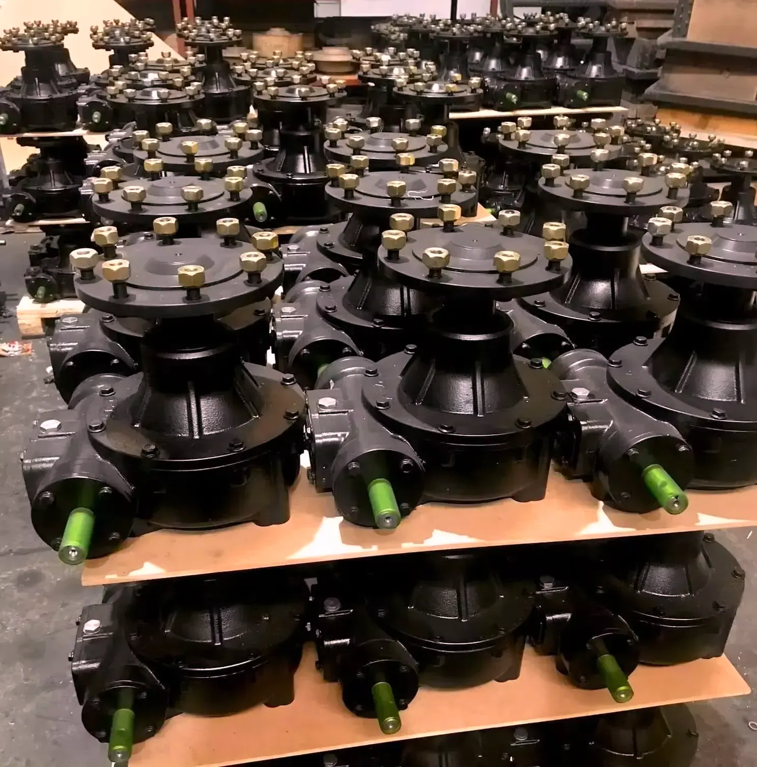
Sourcing and Documentation for Lifting Equipment Gearboxes
Lifting equipment gearboxes require more detailed procurement documentation than most other industrial applications. In addition to the standard dimensional and performance data, the specification must state the AS 1418 duty class (M3 through M8), the required static and dynamic load ratings, the brake specification and engagement sequence, and the documentation requirements for AS 1418 plant registration. For hoist applications involving custom shaft interfaces, accurate drive shaft dimensional and tolerance data is essential to ensure the gearbox output shaft mates correctly with the drum flange without costly field machining.
We supply hoist and crane gearboxes suitable for AS 1418 applications across Australia. Browse available lifting equipment drive solutions on our worm gearbox and hoist drive solutions page, or contact our engineering team with your duty class, SWL, and operating cycle frequency for a specification-matched recommendation.
Frequently Asked Questions
Practical answers to common questions from engineers and maintenance supervisors specifying lifting and hoisting gearboxes for Australian operations.
1. What is the difference between a hoist duty class and a service factor?
+
A service factor is a single multiplier applied to static torque to account for non-uniform loading — it does not incorporate the cumulative fatigue damage that cyclic lifting loads impose on gear teeth and bearings over thousands of operating cycles. The FEM/ISO duty class system (M1–M8) used in AS 1418 is a fatigue-based classification that combines two variables: the load spectrum class (what fraction of lifts are at or near the rated load) and the total number of operating cycles over the equipment design life. Together they determine a dynamic loading multiplier that for M5–M8 duty cranes can be 2.5–4× the static load. Specifying a hoist gearbox on service factor alone without reference to AS 1418 duty class is technically non-compliant and potentially unsafe.
2. Can a worm gearbox be used as the sole load-holding device on a hoist?
+
No — not for any hoist classified M3 and above under AS 1418. Self-locking in a worm gearbox is friction-dependent and varies with temperature and lubrication condition. A warm, freshly lubricated worm at high ratio has reduced self-locking margin compared to a cold, dry unit. AS 1418 requires a separately rated mechanical brake capable of holding 150% of the rated hoist load with motor power removed, as the primary load-holding device. Worm self-locking may be used as a supplementary feature in light workshop hoists below M3 duty, but even in that case, a motor brake is strongly recommended as the primary safety mechanism.
3. What documentation is required for AS 1418 crane registration in Australia?
+
Plant Design Registration for a crane or hoist in Australia requires: the design documentation verifying compliance with AS 1418 (or equivalent); a Design Registration number issued by SafeWork or the relevant state authority; structural calculations for rated SWL; electrical schematic showing control and brake logic; gearbox and drivetrain specifications including duty class, rated torque, and brake rating; and test certificates from the initial load test (typically 110% of SWL). The gearbox supplier should provide the AS 1418 duty class confirmation, dynamic load rating at that class, and brake test certificate as part of the standard delivery documentation package. Missing any of these delays registration, which delays the crane being legally placed into service.
4. How is the gear ratio selected for an electric wire rope hoist?
+
The gear ratio is selected to achieve the required hook speed from the available motor speed. Hook speed (m/min) = (π × drum diameter in metres × gearbox output shaft RPM) / reeving factor. Required output shaft RPM = (hook speed × reeving factor) / (π × drum diameter). Gear ratio = motor RPM / output shaft RPM. For example, a 2-reeved hoist with a 400 mm drum targeting 10 m/min hook speed with a 1,450 RPM motor: output shaft RPM = (10 × 2) / (π × 0.4) = 15.9 RPM; gear ratio = 1,450 / 15.9 = 91.2:1. Select the nearest standard ratio — typically 90:1 or 100:1 for this application range.
5. What causes premature gear failure on overhead crane hoists?
+
The three most common root causes of premature hoist gearbox failure are: underspecification for the actual duty class (the hoist is used more intensively than its M-class rating accounts for, accumulating fatigue damage faster than the design life); oil contamination through deteriorated seals allowing metallic wear debris to circulate and accelerate tooth flank wear; and insufficient brake adjustment allowing the hoist to start under dynamic braking conditions rather than clean motor acceleration, imposing impact torques on the gear mesh at every start. Regular oil analysis, annual seal inspection, and brake gap adjustment to the manufacturer’s specification are the three maintenance activities that most directly extend hoist gearbox service life.
6. Is a VFD appropriate for a lifting hoist drive?
+
Yes — VFD-controlled hoist drives are widely used on modern cranes and hoists for smooth acceleration, variable speed positioning, and controlled lowering. The safety-critical consideration is the brake and VFD control interlock: the VFD must not drop to zero speed while maintaining motor torque before the brake is confirmed engaged. Most modern hoist VFDs include dedicated safe-torque-off (STO) and safe-brake-control (SBC) safety functions for exactly this purpose. The gearbox must be verified against the VFD’s peak torque output capacity — which on a modern hoist drive may be 200% of rated motor torque during controlled deceleration — as this can exceed the gearbox dynamic load rating if not accounted for in the specification.
7. How often should a crane hoist gearbox be inspected?
+
AS 1418 and state WHS plant maintenance requirements define both the type and frequency of crane inspection. For a registered overhead crane, a formal plant inspection by a competent person (typically a licensed crane inspector) is required at intervals not exceeding the manufacturer’s recommended service interval — in practice, annually for most workshop cranes, and 6-monthly for high-duty port and mining cranes. In addition to the statutory inspection, operators should conduct pre-use checks at every shift start and oil level checks monthly. The gearbox specifically should have oil analysis conducted annually and seals inspected for leakage quarterly. For very high-duty installations (M7–M8), oil analysis every 1,000 operating hours is the industry standard.
8. What documentation should a hoist gearbox supplier provide with delivery?
+
A lifting equipment gearbox delivery package should include: dimensional GA drawing; rated static and dynamic output torque at the specified AS 1418 duty class; gear ratio; output shaft and bore dimensions; brake torque rating and engagement sequence description if integrated; material test certificates for gear, shaft, and housing materials; gear and bearing L10 life calculations at rated dynamic load; IOM manual with installation, oil fill, first-run, and maintenance procedures; and Safety Data Sheet for the supplied lubricant. For AS 1418 plant registration, the documentation must also confirm the specific duty class (e.g., M5), the associated dynamic loading factor used in the gear rating, and the design standard to which the unit was designed. Assembling this package from the supplier after delivery adds weeks to the registration process.
Get an AS 1418-Compliant Hoist Gearbox Specification
Share your SWL, duty class, hook speed, and drum diameter — our engineers will return a complete gearbox specification with duty rating confirmation and brake recommendation within one business day.
Request a Free Hoist Drive Specification →
