
Bucket Elevator Drive Systems · Industrial Gearbox Engineering · Australia
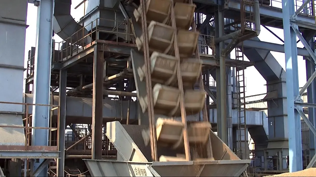
Technical Specifications
The table below summarises the standard engineering parameters used when selecting a gearbox for bucket elevator drive applications. Values span light agricultural grain elevators through to heavy industrial cement and mineral processing installations common across Australian operations.
| Parameter | Typical Range | Notes |
|---|---|---|
| Output Torque | 50 – 80,000 N·m | Cement and ore elevators at upper end |
| Gear Ratio | 10:1 – 80:1 | Higher ratios for slow-speed heavy chain elevators |
| Head Pulley Speed | 30 – 120 RPM | Belt speed 1–3.5 m/s for centrifugal discharge |
| Input Speed | 960 – 1,500 RPM | Standard 4-pole / 6-pole motor |
| Service Factor (SF) | 1.5 – 2.5 | Higher than conveyor due to starting conditions |
| Mechanical Efficiency | 78 % – 97 % | Worm lower; helical-bevel upper |
| Mounting | Shaft-mount (hollow bore), foot-mount | Shaft-mount dominant on modern elevators |
| Backstop Requirement | Mandatory (all designs) | Prevents loaded bucket rollback on power loss |
| IP Rating | IP55 – IP66 | Dusty grain and mineral environments need IP65+ |
| Lubrication | ISO VG 220–460 gear oil | Synthetic oil recommended above 35°C ambient |
Where Bucket Elevators Need Gearboxes — and Why
A bucket elevator is deceptively simple in appearance — a loop of belt or chain with cups attached, running up a casing. The drivetrain reality is more demanding. At the moment of startup from rest with a fully loaded elevator, the gearbox must overcome the gravity load of every filled bucket simultaneously. At shutdown, a backstop must hold the entire loaded string against reversing. Each drive position on a bucket elevator imposes conditions that require deliberate engineering choices — not catalogue defaults.
Head Section: The Primary Drive Position
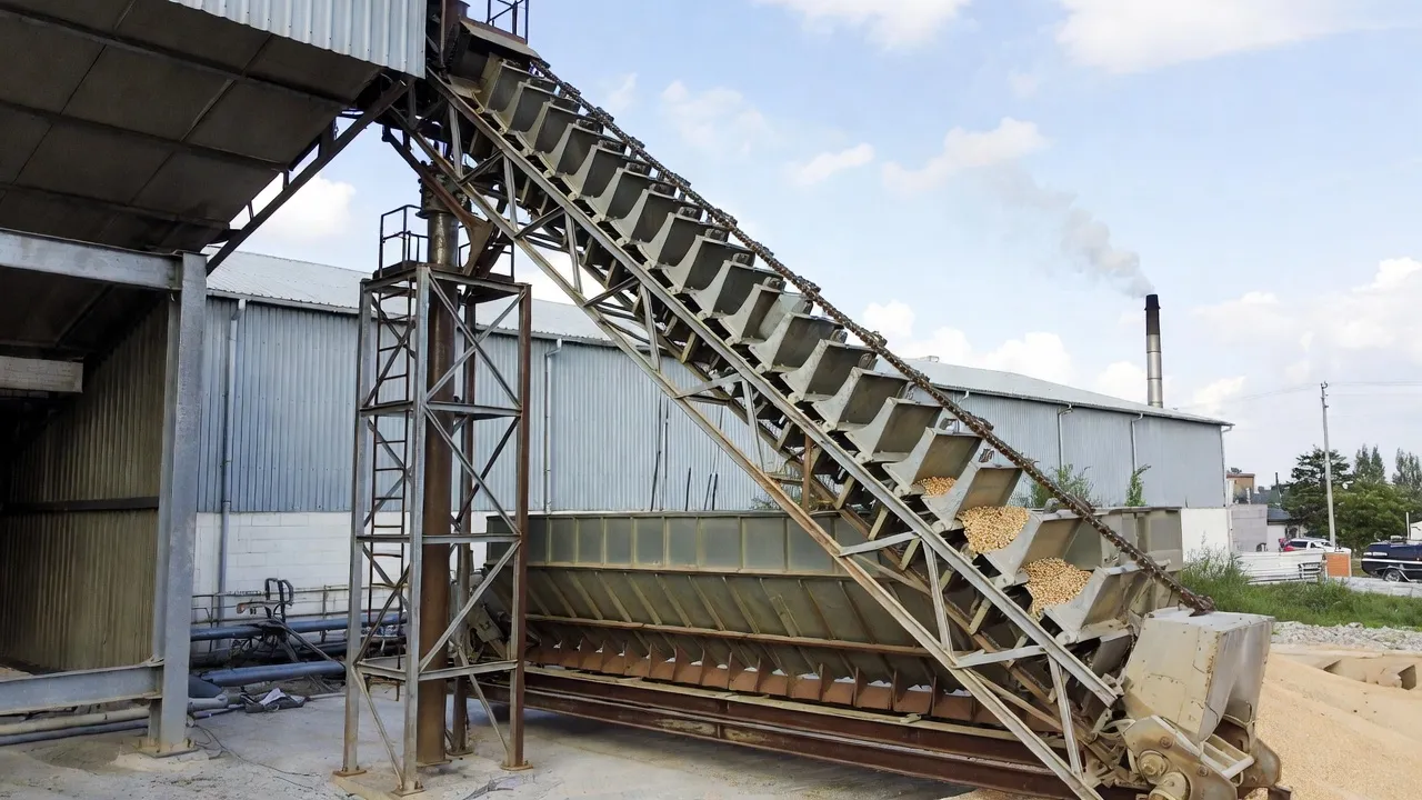
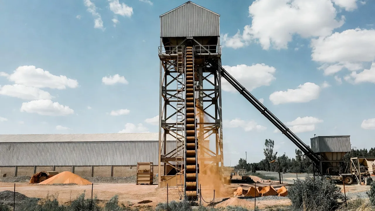
The head section sits at the top of the elevator casing and houses the head pulley or sprocket around which the belt or chain passes to discharge material centrifugally or by gravity into the discharge chute. This is where the bucket elevator gearbox is always located. The gearbox must deliver sufficient output torque to accelerate the fully loaded bucket string from rest — a condition that demands starting torque 2–3× the running torque — and then sustain continuous rated torque for hours without overheating. The head section is also spatially constrained: the casing width leaves limited room on either side of the pulley shaft, making compact shaft-mounted configurations the dominant choice across most designs above 5 kW.
For centrifugal discharge elevators handling grain, fertiliser, or dry chemicals, head pulley speeds of 40–100 RPM are typical, requiring gear ratios of 15:1 to 35:1 from a 1,450 RPM motor. Positive-discharge and continuous-bucket elevators run the head sprocket more slowly — sometimes below 30 RPM — pushing ratios toward 50:1 to 80:1 and often favouring a two-stage helical-bevel unit or a worm gearbox for the high ratio in a single compact assembly.
Boot Section: Belt Take-Up and Tension Management
The boot sits at the base of the elevator and houses the tail pulley or sprocket, which is adjustable to maintain correct belt or chain tension. Most modern bucket elevators use a screw take-up adjustment in the boot — a manually or motor-driven lead screw that repositions the tail pulley axially. When a powered take-up is specified for a large elevator, the drive is a low-power worm gearbox or worm gear motor unit acting on the lead screw, providing the fine tension adjustment and self-locking position hold that keeps the belt taut between service intervals. The take-up drive is intermittent in duty — it operates only when tension has drifted — and its specification is entirely secondary to the main head drive gearbox.
Special Configuration: Twin-Drive Elevators
Very tall elevators — those exceeding 50 metres in height and carrying chains of several tonnes — sometimes employ twin drive heads mounted at the top of each casing side, each driven by its own motor and gearbox pair acting on the same head shaft through synchronised shaft connections. This arrangement halves the torque demand on each gearbox and allows the use of two smaller, more readily stocked units rather than one large custom unit. Synchronisation between the two drives is achieved through the rigid coupling at the head shaft; the gearboxes do not need to be electronically synchronised, simplifying the control scheme considerably compared to a twin-drive belt conveyor where slip between separate drive pulleys requires careful VFD coordination.
Choosing the Right Gearbox Type for Bucket Elevator Duty
The three gearbox types used in bucket elevator applications each suit a specific combination of power level, required ratio, space envelope, and operating duty. Understanding the genuine trade-offs — rather than defaulting to the cheapest or most familiar option — produces a drivetrain that runs the full design life without premature failure.
Right-angle, single-stage ratios to 80:1; self-locking above 25:1; compact footprint for narrow elevator casings. Efficiency 78–92% depending on ratio and load. Preferred for agricultural grain elevators below 15 kW and for take-up and positioning drives. The self-locking characteristic eliminates the need for a separate backstop device in some configurations, simplifying the drive assembly.
Right-angle with helical stages; efficiency 94–97%; high torque density; long service life under continuous duty. The benchmark choice for industrial bucket elevators above 15 kW in cement, mining, sugar, and port operations. Available as shaft-mounted hollow-bore units that connect directly to the head pulley shaft without a separate coupling, reducing installation complexity and potential misalignment issues.
Two-stage: helical first stage for efficiency, worm second stage for ratio and self-locking. A useful middle ground where a standard worm unit lacks the efficiency for continuous duty but a helical-bevel unit is larger than necessary. Common in mid-range agricultural elevators of 7.5–22 kW and in continuous-bucket food processing elevator installations requiring quiet operation and self-locking safety at ratios above 40:1.
Gear Ratio, Torque Sizing, and Service Factor Selection
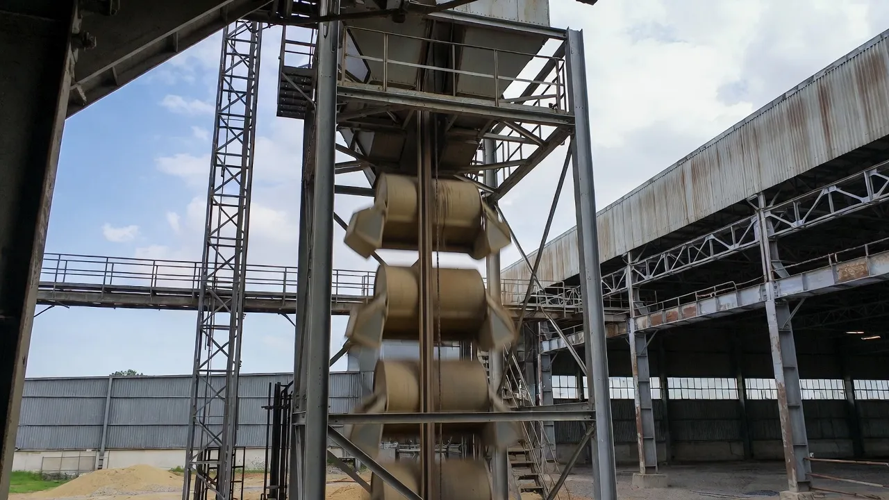
Bucket elevator sizing starts from the head pulley speed requirement, which is determined by the material and discharge type, then works backward through the gear ratio to the motor. Getting this sequence right is the difference between a correctly sized drivetrain and one that either races through fine material or stalls under a heavy ore load.
Calculating the Required Head Pulley Speed
For centrifugal discharge elevators, the critical design parameter is the bucket peripheral speed at the moment of discharge. The discharge trajectory depends on the relationship between centrifugal force and gravity: the material must leave the bucket before it reaches the top of the arc, not linger and fall back into the boot. The optimal belt speed varies by material — grain typically requires 1.5–2.5 m/s, while denser materials like fertiliser pellets or fine ore need 1.2–1.8 m/s to avoid over-throw or material degradation. Belt speed (v, m/s) equals π × D × n / 60, where D is the head pulley diameter in metres and n is pulley speed in RPM. Rearranging: n = 60v / (π × D). For a 400 mm head pulley at 2.0 m/s belt speed: n = 60 × 2.0 / (π × 0.4) = 95.5 RPM. With a 1,450 RPM motor, the required ratio is approximately 15.2:1.
Output Torque and the Elevator Load Calculation
The effective pull at the head pulley of a bucket elevator combines three components: the weight of material in the filled buckets on the ascending side (minus the material on the descending side for continuous-bucket designs), the belt or chain self-weight differential between ascending and descending runs, and the friction losses in the casing guides and boot bearing. For a loaded elevator of total capacity 50 tph with a bucket spacing of 300 mm and 20-litre buckets, the ascending material load at any instant can reach 400–600 kg — producing a head pulley tangential force of 4,000–6,000 N at a 400 mm pulley radius, and an output shaft torque of 800–1,200 N·m. This is the continuous running torque; the gearbox must be rated at this figure multiplied by the service factor.
Why Bucket Elevators Demand a Higher Service Factor
Bucket elevators are the most demanding application in bulk material handling for gearbox starting torque. Unlike a belt conveyor that starts under moderate load (the belt is already tensioned and the material is supported along its length), a bucket elevator starts with the full weight of every bucket of material hanging from the head pulley. The starting torque can reach 3–5× the rated running torque depending on the number of filled buckets and the height of the elevator. A minimum service factor of 1.75 is required for direct-on-line motor starting, rising to 2.0–2.5 for tall elevators above 20 metres, elevators handling heavy dense materials, and those subject to jam conditions from oversized lumps or wet material bridges. Applying an adequate service factor at design stage costs a fraction of what a gearbox replacement in a 30-metre-high elevator head costs in production loss and access equipment.
Backstop Devices: The Non-Negotiable Safety Component
A backstop — also called a holdback or anti-runback device — is mandatory on every bucket elevator drive without exception. When power fails or the motor trips, gravity immediately begins pulling the loaded ascending side of the belt or chain backward, toward the boot. Without restraint, a fully loaded 25-metre tall grain elevator can reach dangerous reverse speed within seconds, tearing the boot apart and discharging tonnes of material backward through the casing. Fatalities have resulted from this failure mode on elevators without functional backstop devices.
The backstop is typically a sprag-type overrunning clutch fitted to the slow-speed output shaft of the gearbox, or to the head pulley shaft directly. It must be rated for the maximum backstop torque — the torque generated by the loaded elevator at rest, which for an inclined or tall elevator significantly exceeds the rated running drive torque. On a 30-metre elevator, the backstop torque can be 1.8–2.5× the running torque. Some gearbox suppliers offer integrated backstop provision as a factory-fitted option on the output shaft housing — this is the preferred arrangement as it ensures the backstop rotation direction is correctly aligned with the gearbox output shaft direction and eliminates the field installation error risk.
For worm gearboxes with ratios above 25:1, the self-locking characteristic of the worm mesh provides some inherent anti-runback resistance. However, self-locking in a worm drive depends on the friction coefficient at the gear mesh, which varies with temperature and lubrication condition. A warm, well-lubricated worm gearbox has lower friction than a cold or dry one and may not reliably hold the load under all conditions. A dedicated sprag backstop provides a positive mechanical lock regardless of gearbox temperature or lubrication state and should always be specified even when a self-locking worm is used.
Installation and Mounting Considerations for Elevator Head Drives
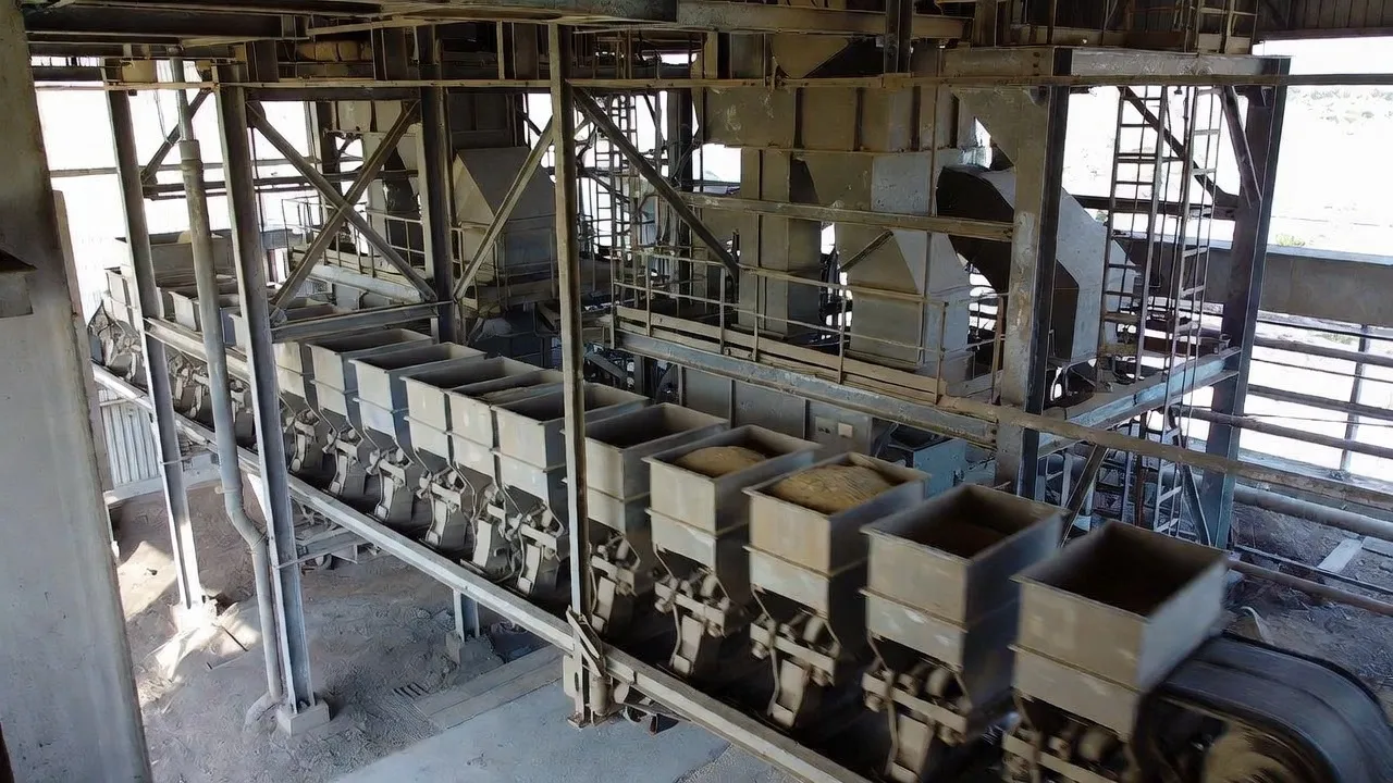
Installing a bucket elevator head drive is more spatially constrained than a typical conveyor drive. The elevator casing sits directly below the head section, leaving limited lateral clearance on either side of the head shaft. Shaft-mounted gearboxes that slide directly onto the head pulley shaft — with a torque arm reacting against the casing structure — make the best use of available space and remove the need for a fabricated baseframe and flexible coupling. The steps below cover the installation sequence that avoids the most common field errors.
Maintenance Strategies for Long-Life Bucket Elevator Drives
Accessing a bucket elevator head drive for maintenance is harder than accessing a ground-level conveyor drive. The combination of height, confined casing structure, and often no permanent access platform means that unplanned maintenance events are significantly more expensive in labour time and elevated work risk than on comparable ground-level drives. A proactive maintenance programme that minimises unplanned interventions pays back many times over in this application.
Oil Management in Elevated and Confined Installations
Changing gear oil on an elevator head drive 20–30 metres up a casing is a working-at-heights task requiring permit, harness, and two-person attendance. Each oil change therefore carries a labour and safety cost that ground-level changes do not. Two strategies reduce the frequency without compromising lubrication quality: using a full-synthetic gear oil (which extends change intervals to 20,000–30,000 hours compared to 10,000–15,000 hours for mineral oil) and installing an oil drain extension tube that allows draining from a ground-level valve without ascending to the head. The latter is a minor modification during installation but saves hours per oil change over the equipment lifetime.
Vibration Monitoring via Remote Sensing
Installing a wireless vibration sensor on the gearbox casing at commissioning time — when scaffold or access equipment is already in place — adds negligible cost compared to the labour and disruption of returning to install it as a retrofit. Continuous or periodic vibration data transmitted to the plant control room or a cloud platform allows bearing defect frequency trending without personnel ascending to the head. Alarm thresholds set at 150% of baseline RMS velocity provide early warning of developing bearing damage 4–8 weeks before audible symptoms appear, allowing planned access rather than emergency response.
Backstop Device Inspection
The sprag backstop should be inspected annually — rotation direction confirmed by hand, outer race examined for wear or scoring, and grease renewed per the manufacturer’s specification. A backstop that has operated correctly for years can seize internally if the sprag cage corrodes or the grease dries out, converting it from a reliable safety device into a rotating mass that offers no anti-runback protection. Annual inspection, compared to the consequence of a runback event, is among the lowest-cost, highest-return maintenance tasks in the entire plant maintenance programme.
Bucket Elevator Gearbox Applications Across Australian Industries
Australia’s reliance on bulk commodity exports — grain, coal, iron ore, sugar, fertiliser — and its extensive domestic cement and food processing industries create a consistent demand for reliable bucket elevator drives across a range of operating environments and duty cycles.
Soft-Start and Variable Frequency Drive Integration
The high starting torque requirement of a loaded bucket elevator makes controlled starting one of the most valuable engineering features a drive system can have. Direct-on-line starting is technically possible but imposes 5–7× rated torque spikes on the gearbox, belt, and head shaft at every start — events that accumulate fatigue damage even if each individual start does not cause visible damage.
A soft starter limits starting current to approximately 250–350% of rated full-load current and ramps the torque gradually over 5–15 seconds, reducing the starting torque spike to 1.5–2× rated. This is adequate for most grain and light material elevators. For heavy ore elevators or those restarting under full load following a power interruption, a variable frequency drive provides better control — full motor flux (and therefore full torque capability) is available from zero RPM, allowing the elevator to accelerate the fully loaded string smoothly through a programmable S-curve ramp without the torque interruptions that soft starters produce near the bottom of the voltage ramp.
When a VFD is specified, the gearbox must be verified against the peak torque the drive can command during acceleration — typically 150–200% of rated motor torque for 60 seconds. Additionally, the backstop must remain correctly oriented and functional under VFD-controlled operation: some backstop designs can chatter at low speeds during the acceleration ramp, requiring the VFD minimum acceleration rate to be set above the threshold at which chattering occurs. The gearbox supplier should confirm compatibility with the specified VFD current limit and acceleration profile before shipment.
Specifying and Sourcing Bucket Elevator Gearboxes in Australia
A precise specification document reduces procurement lead times and eliminates the risk of receiving an undersized unit. The minimum specification for a bucket elevator gearbox should state: rated output torque (N·m, not just motor power); required gear ratio or output speed; input speed; mounting configuration (shaft-mount bore diameter, or foot-mount flange size); service factor; ambient temperature range; IP rating; special requirements such as food-grade lubricant, ATEX certification, or integrated backstop provision; and the required documentation package including dimensional drawings and test certificates.
For applications where the output shaft connects to a custom head pulley shaft via a hollow-bore connection, dimensional accuracy on both the shaft and bore is critical. Specifying the correct shaft tolerance class (typically k6 for interference fit or h6 for sliding fit) and confirming the keyway dimensions prevents the most common field fitment problem: a bore that will not slide over a nominally correct shaft because the tolerance classes were not coordinated between the shaft machinist and the gearbox bore. A supplier with experience in elevator drivetrain supply — rather than a general industrial supplier who happens to stock gearboxes — will flag this coordination requirement without being asked. Correctly specified drive shaft dimensions and fit tolerances should always be provided alongside the gearbox specification for shaft-mounted configurations.
Our engineering team stocks and supplies helical-bevel and worm gearboxes for bucket elevator applications across Australia, with shaft-mounted hollow-bore units available in common head shaft diameters from 40 mm to 180 mm. Browse the full range on our worm gearbox and elevator drive solutions page, or submit your application data directly to contact our engineering team for a specification recommendation and lead-time confirmation within one business day.
Frequently Asked Questions
Practical answers to the questions most commonly asked by engineers, maintenance planners, and procurement teams specifying bucket elevator drives for Australian operations.