
Screw Conveyor & Auger Drive Systems · Industrial Gearbox Engineering · Australia
Technical Specifications
The parameters below cover the standard engineering range for screw conveyor and auger gearbox applications, from compact agricultural portable augers through to heavy industrial inclined cement and mineral processing screws found across Australian operations.
| Parameter | Typical Range | Notes |
|---|---|---|
| Output Torque | 30 – 50,000 N·m | Heavy inclined cement screws at upper end |
| Gear Ratio | 7.5:1 – 100:1 | Higher ratios for slow-speed heavy screws |
| Screw Speed | 10 – 200 RPM | Grain augers higher; sludge screws lower |
| Input Speed | 960 – 1,500 RPM | 4-pole or 6-pole motor standard |
| Service Factor (SF) | 1.25 – 2.0 | Higher for lump-prone or abrasive materials |
| Mechanical Efficiency | 78 % – 97 % | Worm lower; helical-bevel higher |
| Mounting | Hollow bore, foot-mount, flange-mount | Hollow bore direct-to-screw shaft most common |
| Output Shaft Loading | High overhung radial load | Critical bearing selection parameter |
| IP Rating | IP55 – IP66 | Dusty grain and mineral applications need IP65 |
| Lubrication | ISO VG 220–460 gear oil | Synthetic recommended for continuous duty above 35°C |
Where Screw Conveyors Need Gearboxes — and What They Demand
Unlike belt conveyors where the drive gearbox sits at a head pulley and the belt bears tension loads along its length, a screw conveyor concentrates all its drive torque at a single point — the screw shaft connection at the drive end. Every metre of screw, every kilogram of material, and every degree of inclination adds to the torque that single gearbox output shaft must deliver. The nature of that load changes significantly depending on whether the screw runs horizontal, inclined, or vertical, and whether the material flows steadily or arrives in irregular slugs.
Horizontal Screw Conveyors: High Radial Load, Steady Torque
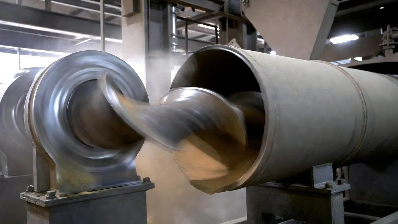
Horizontal screws — the most common configuration across Australian grain handling, food processing, and mining operations — present a gearbox load profile dominated by material friction rather than gravity. The torque required to rotate the screw against the dragging resistance of bulk material pressing against the trough wall is relatively constant once the conveyor reaches steady-state operation, which makes accurate sizing straightforward. The critical gearbox parameter often overlooked on horizontal installations is the overhung load on the output shaft — when the gearbox output shaft connects directly to the screw shaft via a coupling, the combined weight of the coupling, screw shaft extension, and any driving forces from material resistance create a radial bending moment on the gearbox output bearing that can cause premature bearing failure if the unit is selected on torque rating alone without verifying the output bearing radial load capacity.
This overhung load is addressed by specifying a screw conveyor-specific gearbox with reinforced output bearing arrangements, or by using a hollow-bore gearbox that mounts directly onto the screw shaft rather than connecting via a coupling — eliminating the overhung moment by distributing the radial load directly through the bore bearing rather than cantilevering it on an output shaft extension.
Inclined Screw Conveyors: Gravity Adds a Second Torque Component
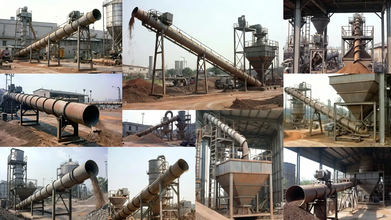
An inclined screw conveyor above 15° requires meaningfully more drive torque than the same conveyor horizontal — the gravity component of material weight acting along the screw axis adds to the friction torque rather than being supported by the trough wall. At 20° inclination, drive power can be 1.4–1.8× the horizontal equivalent for the same material and throughput. At 45°, the factor rises to 2.5–3.5×. Australian grain receival facilities frequently use inclined augers to transfer grain from trucks into bins at 35–50° inclination; portable agricultural augers operate at similar angles. Every one of these applications demands a gearbox sized for the inclined duty, not the horizontal figure — a distinction that catalogue selection tools do not always make clear without active user attention.
A further consideration specific to inclined screws is the requirement for a backstop or anti-rollback mechanism. When the motor stops, inclined screws carrying a full load of grain, sand, or ore can reverse under gravity, running the screw backward and discharging material at the boot rather than the discharge end. While worm gearboxes with ratios above 30:1 provide inherent resistance to this reversal through friction, the same caution applies here as to bucket elevators — self-locking worm friction is temperature-dependent and a warm, freshly lubricated gearbox provides less rollback resistance than a cold one. An external backstop device is the safe engineering choice for inclined screws above 25° that carry significant material loads.
Vertical Screw Conveyors and Bin Discharge Augers
Vertical screw conveyors and bin discharge augers represent the highest torque-to-power ratio application in the screw conveyor family. A vertical screw lifting material straight up against gravity generates axial thrust on the screw shaft — a combined thrust-and-torque loading that requires both adequate gearbox output torque and a thrust bearing arrangement at the lower end capable of carrying the full material column weight. Live-bottom bin discharge augers beneath storage silos impose variable loading as the bin empties: initial high resistance from a full head of material, decreasing as the bin level drops. The gearbox must handle the maximum (full bin) condition without overheating; many installations choose oversized units specifically to address the thermal load during the demanding initial extraction phase.
Gearbox Types for Screw Conveyor Applications
The screw conveyor is, historically, the application that made the worm gearbox an industry standard — and worm gearboxes still dominate the category. But the choice is not automatic, and selecting the wrong type for the power level, duty cycle, or environmental conditions produces service problems that could have been avoided at specification stage.
Right-angle drive; single-stage ratios to 100:1; compact footprint that suits the confined space at a screw conveyor drive end. Efficiency 78–92%. The dominant choice for most screw conveyor applications across Australian agriculture, food processing, and mining below 22 kW. Self-locking above 30:1 provides passive rollback resistance on inclined screws. Bronze worm wheel tolerates short-duration jam loads better than helical gears, making it forgiving in applications where material lumps cause brief overloads.
Right-angle with helical stages; efficiency 94–97%; suited to continuous heavy-duty screw conveyors above 22 kW that run 16–24 hours per day in cement plants, mineral processing facilities, and port bulk terminals. Lower heat generation per kW of power transmitted compared to worm types — a significant advantage in Australian high-ambient-temperature environments where worm gearboxes on continuous-duty drives regularly require cooling fans to maintain oil temperature within limits.
Parallel shaft; motor and gearbox integrated as a single unit; suits screw conveyor drives where the motor can run parallel to the screw axis — less common than right-angle designs but preferred in long horizontal installations where the drive-end clearance permits the motor to extend axially. Highest efficiency of the three types; minimal heat generation; direct IEC flange motor replacement simplifies future motor changes.
Gear Ratio, Torque Calculation, and the CEMA Sizing Method
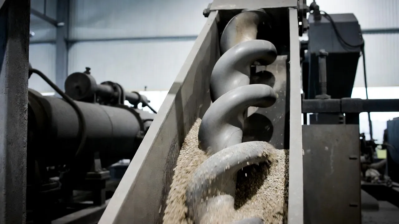
Screw conveyor power and torque calculation is more standardised than most bulk material handling applications, with CEMA (Conveyor Equipment Manufacturers Association) providing the widely adopted method used by Australian engineering firms. The CEMA approach combines material-dependent friction factors, conveyor geometry, and inclination angle to produce a required drive power and, from that, the required output shaft torque at the specified screw speed.
The CEMA Drive Power Calculation
The CEMA formula for horizontal screw conveyor drive power is: HPf = L × N × Fd × Fb / 1,000,000 for friction HP, plus HPm = C × W × L × Fo / 1,000,000 for material HP. In metric terms, total drive power (kW) = [(conveyor length in metres × screw speed in RPM × friction factor × bearing factor) + (capacity in t/h × conveyor length × material factor)] / conversion constant. Material factors (Fm) range from 0.5 for light free-flowing dry grain to 4.0 for heavy, abrasive materials such as wet sand, iron ore fines, or cement clinker. These factors directly multiply the material-carrying power component and represent the single largest variable in screw conveyor power sizing.
Converting Drive Power to Output Torque and Gear Ratio
Once drive power (kW) and screw speed (RPM) are established, output torque is T = (9,550 × kW) / n, where n is the screw RPM. Gearbox ratio is then i = n_motor / n_screw. For example, a 7.5 kW screw running at 55 RPM produces T = (9,550 × 7.5) / 55 = 1,302 N·m at the screw shaft. With a 1,450 RPM motor, the required ratio is 26.4:1. Applying a service factor of 1.5 for a moderately abrasive material, the gearbox should be rated at 1,302 × 1.5 = 1,953 N·m — pointing to a worm gearbox in the IEC 100 to IEC 112 frame range depending on the supplier’s catalogue.
Inclined Screw Power Uplift
For inclined screws, the CEMA method adds an inclination power factor — published as a multiplier on the horizontal power requirement. At 15° inclination the factor is approximately 1.15; at 25° it is 1.5; at 45° it approaches 2.5. These multipliers apply to the material-carrying component of power only, not the empty running friction component. The practical implication is that a screw conveyor designed for a flat-site installation that is later re-deployed at 30° inclination will be significantly undersized and the gearbox will overheat within hours of operation. Always confirm the installation angle at the time of specification — angular changes of even 10° have a substantial effect on power demand for most bulk materials.
Overhung Load: The Most Overlooked Screw Conveyor Gearbox Parameter
Most engineers specify screw conveyor gearboxes on output torque and gear ratio alone. The output bearing radial load — often called overhung load (OHL) — receives far less attention but is responsible for a significant fraction of screw conveyor gearbox premature failures in the field.
When a gearbox output shaft connects to the screw via a roller chain drive, chain coupling, or V-belt secondary reduction, the tension of the chain or belt creates a radial force on the gearbox output shaft. This force acts as a bending load on the shaft and its supporting bearing — the output bearing must carry both the tangential drive torque and this radial bending simultaneously. For worm gearboxes with inherently compact output bearing arrangements, overestimating the allowable OHL leads to rapid bearing fatigue even when the torque rating is adequate.
The manufacturer’s OHL rating is published in the catalogue as a radial force in Newtons at a specified distance from the bearing face. If the actual installation produces an OHL greater than this figure — which is common when a chain drive adds wrap tension to an already heavily loaded shaft — the bearing L10 life collapses from the catalogue 20,000 hours to a fraction of that. Solving this at specification stage is straightforward: either select a gearbox with a higher OHL rating, specify a hollow-bore shaft-mounted unit that eliminates the coupling overhang load entirely, or redesign the secondary drive to reduce chain tension by using a two-strand chain rather than one.
Installation Configurations for Screw Conveyor Drive Ends
Screw conveyor drive end arrangements vary considerably between applications — a portable farm auger uses a completely different connection method from a fixed industrial screw conveyor in a cement plant. The four configurations below cover the dominant installation approaches encountered across Australian operations.
Maintenance Practices That Prevent Premature Gearbox Failure
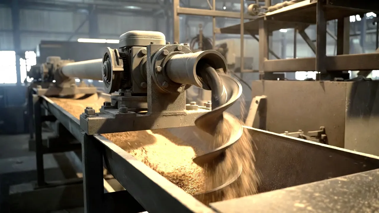
Screw conveyor gearboxes fail for a predictable set of reasons. Oil contamination from material ingress through deteriorated shaft seals, insufficient oil level due to infrequent checks, and worm wheel wear from sustained operation above the thermal rating account for the majority of early-life failures. None of these requires exceptional maintenance skill to prevent — they require structured, scheduled attention to a short list of items.
Seal Integrity: The First Line of Defence
The output shaft of a screw conveyor gearbox operates in the most contaminated part of the conveyor system — immediately adjacent to the material flow and often subjected to dust, moisture, grain husks, mineral fines, or sludge that probes every path into the gearbox housing. A single-lip shaft seal that was adequate at commissioning can allow material ingress within 6–12 months on a heavily loaded agricultural screw, particularly when the screw is run at high throughput and material presses against the seal face from the trough side. Upgrading to double-lip seals with an external labyrinth shield at commissioning — not as a retrofit after the first seal failure — is a low-cost modification that substantially extends the interval before material contamination degrades the gear oil. Monthly visual inspection for oil staining at the output shaft seal and annual seal replacement as a scheduled maintenance item are the practical standard for continuous-duty screw conveyor drives in Australian mining and processing applications.
Oil Level, Oil Quality, and Change Intervals
Worm gearboxes on inclined screw conveyors can experience oil level migration if the oil fill level was set with the gearbox in its horizontal shipping position but operated at 30–45° inclination. A gearbox filled to the correct level when horizontal may have inadequate oil covering the worm gear mesh when tilted — the oil pool shifts toward the lower end of the casing and the mesh runs partially dry. Always set oil level with the gearbox installed at its operating angle, not from the dipstick or level plug position on the flat. For worm gearboxes on horizontal conveyors, the oil should cover the worm wheel to at least one-third of the wheel diameter depth; for inclined units, confirm the adequate coverage with the manufacturer’s installation drawing. Oil change intervals follow the same logic as other industrial gearboxes: 500 hours for the first change, then 5,000–8,000 hours for mineral oil or 15,000+ hours for synthetic, subject to regular analysis.
Thermal Management on Continuous-Duty Drives
Worm gearboxes running at 75–90% of their thermal limit in moderate-temperature environments reach their thermal limit rapidly when ambient temperature rises seasonally, or when additional heat is applied from nearby process equipment. A surface-mounted thermocouple on the gearbox casing — connected to the plant control system or a standalone alarm module — provides the earliest warning of thermal margin reduction. Where gearbox casing temperature exceeds 80°C continuously, an externally mounted cooling fan or oil-to-air radiator should be added. Ignoring thermal warning signs and allowing sustained operation at casing temperatures above 90°C accelerates lubricant oxidation in mineral oil drives, reducing the oil’s film-forming ability and shortening worm wheel bronze life dramatically. A cooling fan that costs $200 is a significantly better investment than a worm wheel replacement that costs $2,000 and requires a 48-hour production stop.
Screw Conveyor Gearbox Applications Across Australian Industries
Australia’s agricultural output, mineral processing capacity, and food manufacturing sector collectively represent one of the largest screw conveyor markets in the southern hemisphere. Each application sector imposes distinct gearbox requirements shaped by its material characteristics, operating schedule, and environmental context.
Variable Speed Control for Screw Conveyors and Feed Rate Management
Screw conveyors are uniquely well-suited to variable-speed operation for process control. Unlike belt conveyors where changing speed significantly affects tensioning and belt-tracking dynamics, a screw conveyor with a VFD-controlled drive can modulate throughput linearly with speed over a wide range — reducing from 100% to 30% speed reduces throughput proportionally with no system instability. This makes VFD-equipped screw conveyors the standard metering device for controlled-feed applications in cement batching, food ingredient dosing, and chemical process feed.
When a VFD is used with a worm gearbox, the minimum operating speed constraint applies: worm gearboxes depend on oil splash lubrication from the rotating worm wheel, and at input speeds below 200–300 RPM, the splash reaching the worm mesh becomes insufficient for full film formation. For applications where very low screw speeds are required — feed screws running at 5–15 RPM — the gearbox input speed at this setting may be below the safe lubrication threshold if a high gear ratio is selected. The solution is either to use a higher gear ratio to keep input speed above the lubrication threshold, to specify forced lubrication on the gearbox, or to select a helical-bevel gearbox that does not have the same minimum-speed lubrication constraint.
Torque ripple from material irregularity on metered-feed screws can cause small speed variations that are visible as output flow variation at high magnification in dosing applications. Closed-loop speed control with encoder feedback from the screw shaft — rather than open-loop VFD frequency control — resolves this in precision dosing applications by correcting for speed variations before they affect the discharge rate measurement.
Specifying and Sourcing Screw Conveyor Gearboxes for Australian Applications
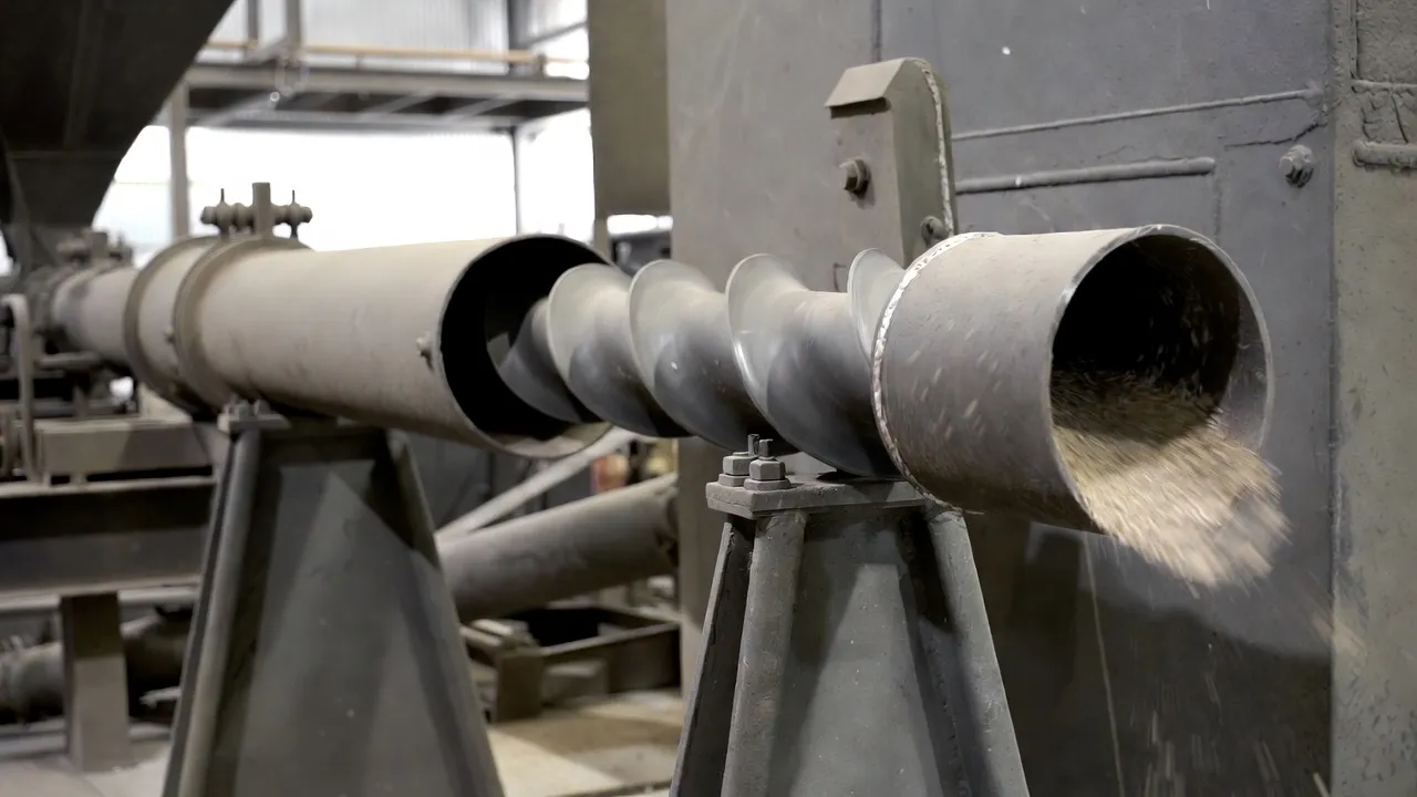
A precise specification document prevents the most common procurement problem with screw conveyor drives: receiving a gearbox that is technically adequate on torque and ratio but fails within months due to an inadequate output bearing OHL rating, insufficient thermal capacity for the ambient temperature, or a shaft bore that does not match the screw shaft without machining. The specification should state as a minimum: required output torque (N·m) at service factor; gear ratio or output speed (RPM); input motor speed; mounting configuration (hollow bore with bore diameter and tolerance class, or foot-mount with output shaft dimensions); OHL requirement in Newtons at installation distance; IP rating; ambient temperature range; and any special requirements such as food-grade lubricant, ATEX certification, or stainless external components.
For continuous industrial screw conveyors in cement, mineral processing, or waste water treatment where production loss from an unplanned gearbox failure has significant consequences, the procurement specification should also include a performance guarantee stating maximum oil temperature rise above ambient at continuous rated load, and minimum L10 bearing life at the specified OHL and output torque. These parameters are rarely volunteered in a standard catalogue submission but are entirely within a reputable supplier’s ability to confirm — and their absence from the quotation is worth clarifying before order placement. Reviewing established worm gear reducer specifications and performance data provides a useful baseline when evaluating competing quotations against one another.
Our engineering team supplies worm gearboxes, helical-bevel units, and gear motors for screw conveyor applications across Australia — from portable agricultural auger drives to large-diameter industrial cement and sludge screw reducers. Browse available configurations on our worm gearbox and screw conveyor drive solutions page, or send your CEMA calculation and installation drawing to contact our engineering team for a specification-matched recommendation within one business day.
Frequently Asked Questions
Practical answers to the most common questions from engineers, maintenance supervisors, and procurement teams working on screw conveyor and auger drive projects across Australia.