Roller Conveyor Drive Systems · Industrial Gearbox Engineering · Australia
Technical Application Reference
Roller conveyors are the backbone of modern production line goods handling and automated material transport — from lightweight carton sortation in e-commerce distribution centres to heavy pallet transfer in automotive manufacturing plants. Each roller in a driven zone requires a correctly specified gearbox to deliver the right speed, the right torque, and the right duty cycle performance. Over-specify and you waste capital; under-specify and you face frequent failures at exactly the moments production pressure is highest. This guide covers the engineering basis for roller conveyor gearbox selection, the drive configurations in common use across Australian operations, and the selection criteria that separate reliable long-term performance from repeat maintenance problems.
Zone Drive & Line-Shaft Configurations
Accumulation & Sortation Systems
Distribution, Automotive & Retail Applications
Technical Specifications
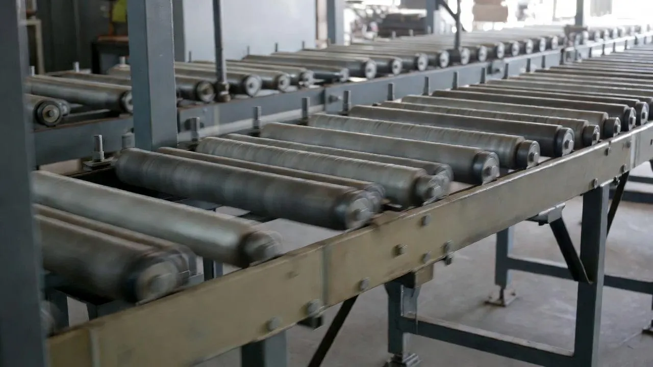
Engineering parameters for gearboxes used in roller conveyor drive applications, from light carton handling in distribution centres to heavy pallet conveyor systems in manufacturing and mining.
| Parameter |
Typical Range |
Notes |
| Output Torque |
5 – 5,000 N·m |
Light carton zones to heavy pallet drives |
| Roller / Conveyor Speed |
10 – 150 m/min |
Accumulation zones at lower end; sortation higher |
| Gear Ratio |
5:1 – 80:1 |
Matched to roller diameter and motor speed |
| Service Factor |
1.25 – 2.0 |
Higher for impact loading at accumulation zones |
| Mounting |
Hollow bore, foot-mount, flange |
Hollow bore direct to roller shaft most common |
| IP Rating |
IP55 – IP65 |
Washdown and dusty environments IP65 |
Drive Configurations for Roller Conveyor Systems
Roller conveyors are configured in two fundamentally different drive architectures, each with distinct gearbox implications. Understanding which configuration is in use — and which is being specified for a new system — determines the gearbox mounting type, torque rating methodology, and control approach.
Zone-Driven (Individual Zone Drive) Systems
In zone-driven roller conveyors, each accumulation zone — typically 1–3 metres long — has its own gear motor mounted at the drive end of the zone. The gear motor drives a powered roller directly via a hollow-bore shaft connection, and the powered roller drives adjacent idler rollers through urethane O-ring or poly-V belt connections. This configuration dominates modern Australian distribution centres and e-commerce fulfilment facilities because it supports zero-pressure accumulation: individual zones can stop independently while adjacent zones continue operating, allowing products to queue without pressure contact that would damage fragile cartons or disturb product orientation.
The gearbox in a zone-driven system is a compact right-angle unit — typically a worm gear motor below 1.5 kW — with a hollow bore that slides directly onto the drive roller shaft and is retained by a torque arm anchored to the conveyor frame. This configuration eliminates coupling alignment, keeps the drive footprint within the conveyor frame width, and allows each zone’s gear motor to be replaced independently without disturbing adjacent zones. The gearbox self-locking characteristic at ratios above 30:1 provides passive holding of accumulated products without requiring the motor to remain energised during the accumulation dwell — a significant energy saving in a system with hundreds of individual zones.
Line-Shaft Driven Systems
Older roller conveyor installations and some heavy-duty production line conveyors use a continuous line shaft running along the length of the conveyor, driven by a single gear motor at one end. Individual rollers are connected to the line shaft via friction-clutch drives or flat-belt connections. The single gearbox in this configuration carries the torque load of the entire conveyor length — potentially hundreds of rollers — and must be sized for the total starting torque of the fully loaded conveyor rather than a single zone. Helical-bevel gearboxes in the 15–75 kW range are standard for line-shaft driven production conveyors.
Line-shaft systems have largely been replaced by zone-driven designs in new Australian installations due to the energy efficiency and flexibility advantages of individual zone control. However, line-shaft conveyors remain in service in older manufacturing plants across Victoria, NSW, and SA, and gearbox replacement for these systems requires matching the original ratio and mounting configuration rather than simply selecting the closest modern catalogue equivalent.
Gearbox Sizing for Roller Conveyor Zones
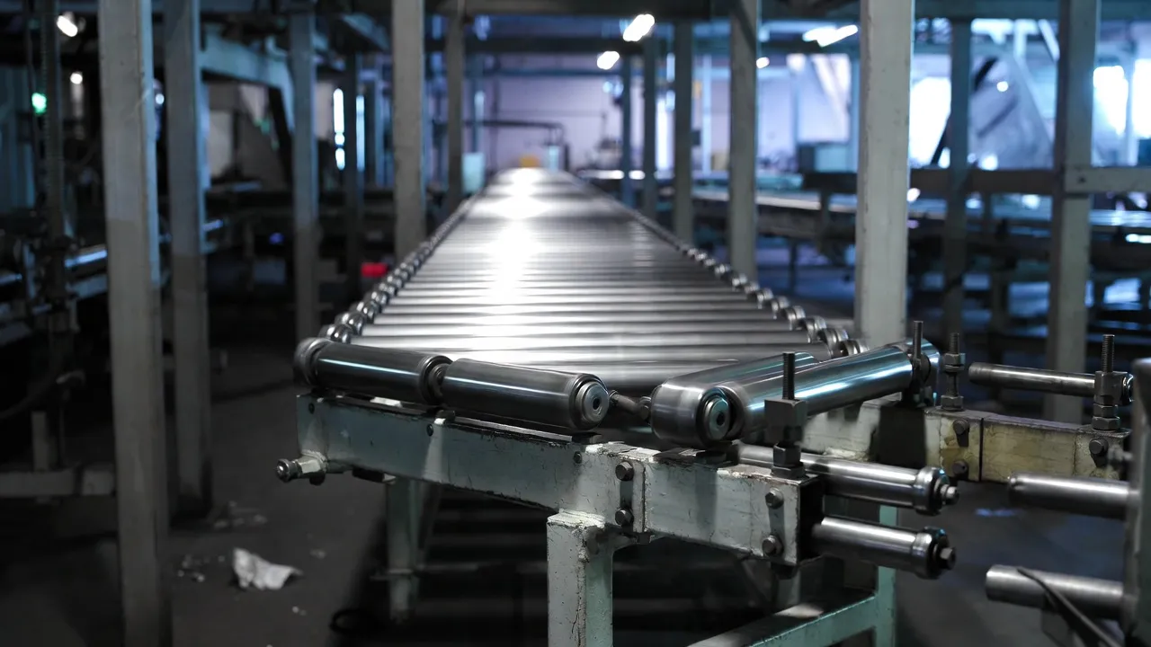
Sizing a roller conveyor zone gear motor requires three parameters: the required roller surface speed (from the conveyor design speed and roller diameter), the required drive torque (from the product load and conveyor friction), and the duty cycle (the fraction of each hour the zone is actively driving product as opposed to accumulating with the motor stopped).
Drive torque per zone = (total product load on zone + zone roller and belt mass) × conveyor friction coefficient × drive roller radius. For a zone carrying 50 kg of product on 80 mm diameter rollers at a friction coefficient of 0.03: drive force = (50 + 8) × 9.81 × 0.03 = 17.1 N; drive torque at 80 mm radius = 17.1 × 0.04 = 0.68 N·m. This is the continuous running torque; the gearbox must also handle the starting torque when the zone motor restarts against a stationary loaded product, which can be 2–3× the running torque. Apply service factor 1.5 for standard distribution centre accumulation conveyors with soft-start or VFD motor control.
Gear ratio = motor speed / required roller speed (RPM). Required roller RPM = (conveyor speed in m/min × 1,000) / (π × roller diameter in mm). For 30 m/min on 80 mm rollers: roller RPM = (30 × 1,000) / (π × 80) = 119 RPM. With a 1,450 RPM motor: ratio = 1,450 / 119 = 12.2:1, rounded to the nearest standard ratio (typically 12.5:1 or 15:1 from most catalogue worm gear ranges).
Gearbox Type Selection for Roller Conveyors
Worm Gear Motor (Zone Drives)
Right-angle compact form; hollow bore for direct roller shaft mounting; single-stage ratios 7.5:1–80:1; self-locking above 30:1; below 1.5 kW covers the vast majority of carton and package zone drives. The dominant choice for modern zone-driven distribution centre conveyor systems in Australia. Standardising on a single frame size and ratio across all zones of similar duty simplifies the spare parts inventory and reduces the SKU count for the facility’s maintenance stock.
Zone-driven DC · Below 1.5 kW · Accumulation and sortation
Helical-Bevel Gear Motor (Main Drives)
Right-angle with high efficiency (94–97%); suited for main conveyor trunk line drives above 2.2 kW, pallet conveyor drives, and inclined sections where continuous high-torque duty would thermally overload a worm unit in Australian summer ambient conditions. Shaft-mounted hollow-bore variants connect directly to the conveyor drive roller shaft and are preferred for new system designs where space constraints and maintenance access are important.
Main trunk drives · Pallet conveyors · Inclined sections
DC Brushless Drum Motor
Integrated gear motor unit sealed within the roller tube; the entire drive is contained inside the conveyor roller with no external components. Increasingly common in modern e-commerce fulfilment systems where ultra-compact, individually controlled zones are required. The internal gearbox is a purpose-built planetary or cycloidal reducer; this is not a field-serviceable unit — the entire drum motor is replaced when worn. Selection follows the same torque and ratio methodology as external gear motors.
Compact zones · E-commerce fulfilment · Clean environments
VFD Control and Energy Efficiency for Roller Conveyor Systems
Variable frequency drive control on roller conveyor gear motors provides speed adjustment for different product types, soft starting to reduce mechanical shock on the gearbox and product, and the ability to slow the conveyor during low-throughput periods — saving significant energy in large distribution centre systems that run 16–24 hours per day.
For worm gear motor zone drives operating at variable speed via VFD, the minimum frequency setting must be confirmed against the worm gearbox’s minimum safe input speed for adequate splash lubrication — typically 300–400 RPM input. At a 15:1 ratio, a 300 RPM minimum input produces 20 RPM minimum output, which corresponds to approximately 5 m/min belt speed on 80 mm rollers — adequate for slow accumulation but not for a very-slow-speed precision positioning application. If the application requires roller speeds below this threshold, either a higher gear ratio or a different gearbox type (helical, which has no minimum speed lubrication constraint) is required.
Roller Conveyor Applications Across Australian Industries
E-Commerce & Distribution
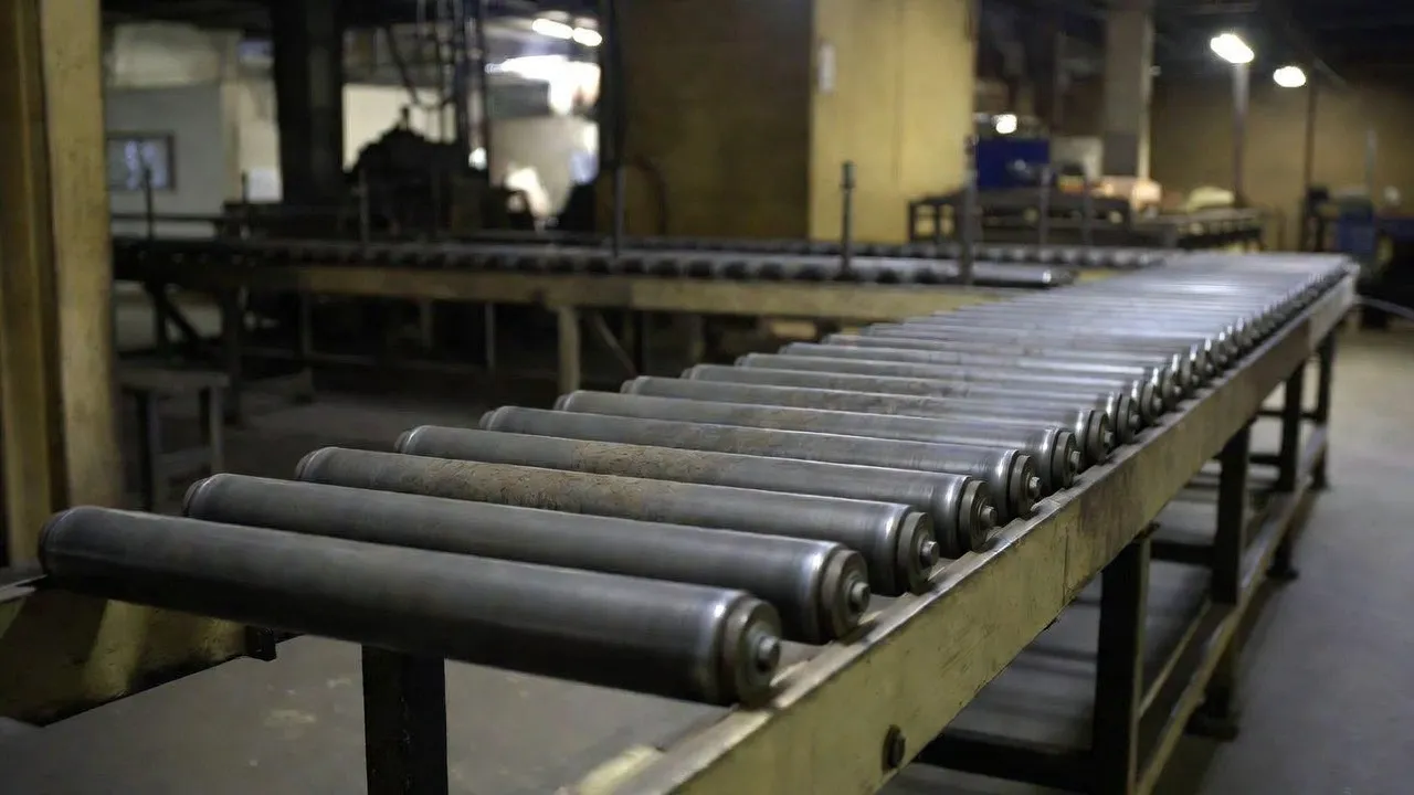
Large Australian e-commerce fulfilment centres operated by Australia Post, Amazon, Catch, and major retailers deploy zone-driven roller conveyors as the primary induction, sortation, and packing infrastructure. These systems may have 500–5,000 individual zone gear motors operating continuously across 16–22 hour operating windows. Standardisation on one or two gear motor models simplifies the maintenance programme and maximises the economies of volume stocking.
Automotive Manufacturing
Roller conveyors in body shop and final assembly plants carry heavy sub-assemblies, engines, and body-in-white structures between assembly stations. These are heavy-duty applications — pallet loads of 500–2,000 kg — requiring helical-bevel drives with service factors of 1.5–2.0 and robust output bearing arrangements for the overhung load of large-diameter drive rollers. Drive standardisation across the plant simplifies the maintenance program and spare parts holding.
Food & Beverage Processing
Food production line roller conveyors handling packaged goods, bottles, cans, and crates require food-grade gear motor construction in washdown zones — IP65 minimum, stainless housings, and NSF H1 lubricants where incidental food contact is possible. High-pressure cleaning twice daily demands gear motors where the housing design avoids food-trapping recesses and all external surfaces are cleanable without disassembly.
Ports & Bulk Terminals
Roller conveyors at Australian port container terminals and bulk handling facilities transport goods between ship, warehouse, and transport interfaces in harsh outdoor environments. IP66 sealing, marine-grade epoxy coating, and stainless fasteners are required at coastal locations. Drives must tolerate salt air, occasional rain immersion during weather events, and the shock loads from heavy containers dropped onto roller surfaces by forklift or crane.
Installation, Maintenance, and Standardisation
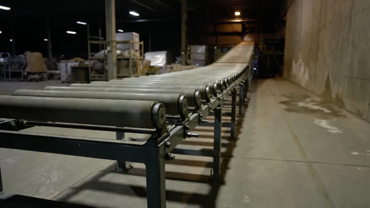
The installation step most frequently missed in roller conveyor gear motor commissioning is the overhung load check. When the gear motor hollow bore connects to a drive roller shaft that also carries chain or belt tension to adjacent idler rollers, the combined radial load from chain wrap tension and product weight can exceed the gear motor’s output bearing OHL rating — the same issue that causes premature bearing failure in screw conveyor and belt conveyor applications. Always calculate the actual OHL at the installation geometry and compare it to the catalogue rated value before finalising the gear motor selection.
For systems with large numbers of identical zones, the maintenance programme should include: 500-hour first oil change on new units to flush break-in debris; oil level check at 6-month intervals; oil change at 5-year intervals or when oil analysis shows contamination; and seal condition inspection at annual service. Many modern worm gear motors for zone drive applications are supplied sealed-for-life with grease-lubricated bearings — confirm whether this applies to the selected unit and whether any periodic maintenance is required.
Detailed worm gear reducer performance data and specifications for roller conveyor zone drive applications are available at our worm gear reducer technical specifications resource. We supply worm gear motors, helical-bevel gear motors, and drum motor gearboxes for roller conveyor systems across Australia. Browse configurations on our roller conveyor drive solutions page, or contact our engineering team with your conveyor speed, product weight, zone count, and ambient conditions for a specification and volume pricing within one business day.
Frequently Asked Questions
Common questions from systems integrators, maintenance engineers, and procurement teams specifying gearboxes for roller conveyor systems.
1. How do I calculate the gear ratio for a roller conveyor zone drive?
+
Required roller RPM = (conveyor speed in m/min × 1,000) / (π × roller diameter in mm). Required gear ratio = motor speed (RPM) / required roller RPM. For example: 40 m/min on 80 mm rollers gives roller RPM = 40,000 / (π × 80) = 159 RPM. With a 1,450 RPM motor, ratio = 1,450 / 159 = 9.1:1. Select the nearest standard catalogue ratio — typically 10:1 for this application. Confirm that at this ratio the actual roller speed is within ±5% of the design speed; a 10:1 ratio produces roller speed of 145 RPM and belt speed of 36.4 m/min at 80 mm diameter, a 9% increase from the target — acceptable for most accumulation applications. Where speed accuracy is critical (product metering), specify the ratio that produces the closest match or use a VFD to fine-tune.
2. Is it better to standardise all zones on one gear motor model or size each zone individually?
+
For systems below 200 zone drives, standardising on a single model almost always produces the best lifecycle outcome. The inventory simplification, maintenance familiarity, and volume pricing typically outweigh the modest energy cost of oversized drives on lighter-duty zones. For systems above 500 zone drives where energy cost is tracked and lifecycle modelling has been completed, segmenting zones into two or three duty classes with a different model for each is worth the added complexity — the energy saving from correctly-sized drives across 500+ motors, running 6,000+ hours per year, can amount to tens of thousands of dollars annually. The decision point is roughly: if energy tracking data shows that oversized zones represent more than 25% of total drive energy consumption, segmentation pays. Below that threshold, standardisation is the practical choice.
3. What causes roller conveyor gear motors to fail more quickly in high-humidity or food processing environments?
+
Two failure mechanisms dominate in humid and washdown environments: seal failure allowing water ingress into the oil, and corrosion of external components starting at fasteners and the housing-to-cover joint. Water contamination of gear oil is the most damaging — even 0.1% water content reduces the oil’s load-carrying capacity and promotes rust on internal gear and bearing surfaces. Preventing this requires IP65 sealing as a minimum (not just IP54), desiccant breathers where thermal cycling causes the gearbox to “breathe” in and out, and double-lip seals at the output shaft rather than standard single-lip seals. For food processing zones subject to high-pressure daily cleaning: specify smooth housing profiles without fins or recesses that trap cleaning water, stainless external fasteners, and confirm the IP65 rating was tested on the complete assembled unit rather than just the housing casting. Annual seal inspection and seal replacement at 3-year intervals prevent the gradual degradation that allows water ingress before it becomes visible externally.
4. What is overhung load and why does it matter specifically for roller conveyor gear motors?
+
Overhung load (OHL) is the radial bending force on the gear motor output bearing from a load applied at a distance from the bearing face — caused in roller conveyor applications by the chain or belt tension of the roller-to-roller O-ring drive between the powered roller and its adjacent idlers. In a zone-driven system, the powered roller may drive 4–8 idler rollers through urethane O-rings, and the tension of all those O-rings adds up to a radial force acting on the drive roller shaft — which is directly connected to the gear motor output. If this combined radial force exceeds the gear motor’s rated OHL at the installation position, the output bearing will develop premature fatigue damage that results in bearing failure well before the end of the expected service life. Always calculate the total O-ring tension for the zone’s roller chain and verify it against the gear motor OHL specification before selecting the unit — this calculation takes five minutes and can prevent a pattern of bearing failures that takes months to diagnose.
5. Can I retrofit VFD control to existing zone gear motors without changing the gearbox?
+
Yes, provided four conditions are confirmed. First, the motor is VFD-compatible — most post-1995 induction motors are, but verify the winding insulation class with the motor nameplate. Second, the gearbox worm mesh lubrication threshold — confirm the minimum VFD frequency does not reduce motor speed below 300–400 RPM input, which is the minimum for adequate worm splash lubrication at the gear mesh. Third, motor cable sizing — VFDs can deliver higher peak current than direct starters; the cable between VFD and motor should be re-rated for the VFD output. Fourth, the torque at low speed — if the application requires holding torque at very low speed (near-stall), confirm the motor can maintain rated torque below 15 Hz without overheating, which requires a motor with integrated thermal protection suitable for VFD duty. Most zone drive retrofits satisfy all four conditions without additional hardware changes.
6. How long should a zone drive gear motor last in a distribution centre application?
+
A correctly specified, correctly installed, and adequately maintained worm gear motor in a distribution centre zone drive application should deliver 40,000–60,000 operating hours before worm wheel replacement is required — equivalent to approximately 7–11 years at 16 hours per day, 365 days per year. In practice, many facilities see 5–8 year gear motor life, with the primary cause of early failure being seal contamination from cleaning operations or overhung load damage from O-ring drive tension that was never calculated. Facilities that manage these two parameters correctly — IP65 minimum sealing with regular seal inspection, and OHL verification during initial system commissioning — consistently achieve the upper end of the expected service life range.
7. What documentation should a roller conveyor gear motor supplier provide?
+
For roller conveyor zone drive procurement, the delivery package should include: dimensional drawing with hollow bore diameter and tolerance, torque arm mounting detail, and overall envelope; rated output torque and gear ratio; output bearing OHL rating at the mounting distance; thermal power rating at the site ambient temperature; lubrication type and fill volume; IP rating certificate; IOM manual with torque arm installation procedure, oil level check, and seal inspection schedule; and for food-grade applications, NSF H1 lubricant certificate and stainless component material certificates. For volume procurement across a large conveyor system, request a manufacturing conformance certificate for the lot confirming all units were manufactured to the same specification and that bore diameter and torque arm dimensions are within the drawing tolerance for direct interchangeability.
Get Roller Conveyor Gear Motors Specified and Priced
Share your conveyor speed, roller diameter, product load, zone count, and ambient conditions — our engineers will return a complete specification with OHL verification and volume pricing within one business day.
Request a Free Conveyor Drive Specification →
