CNC Feed Mechanism & Rotary Table Drive Systems · Precision Gearbox Engineering · Australia
Technical Application Reference
CNC machine tool feed mechanisms and rotary tables represent perhaps the most exacting gearbox application in manufacturing — the dimensional tolerance of a finished part is a direct function of the gearbox’s backlash, torsional stiffness, and speed stability during every cutting pass. A ±5 arc-minute backlash that would be insignificant in a conveyor drive translates to 0.073 mm of positioning uncertainty at a 50 mm rotary table radius — ten times the tolerance on a precision aerospace component. This guide covers the complete engineering basis for CNC feed drive and rotary table gearbox selection, from the calculation methodology that links backlash to machining accuracy, to the specification and sourcing process for Australian precision engineering operations.
Linear Axis & Rotary Table Drives
Zero-Backlash & Torsional Stiffness
Aerospace, Toolmaking & Precision Engineering
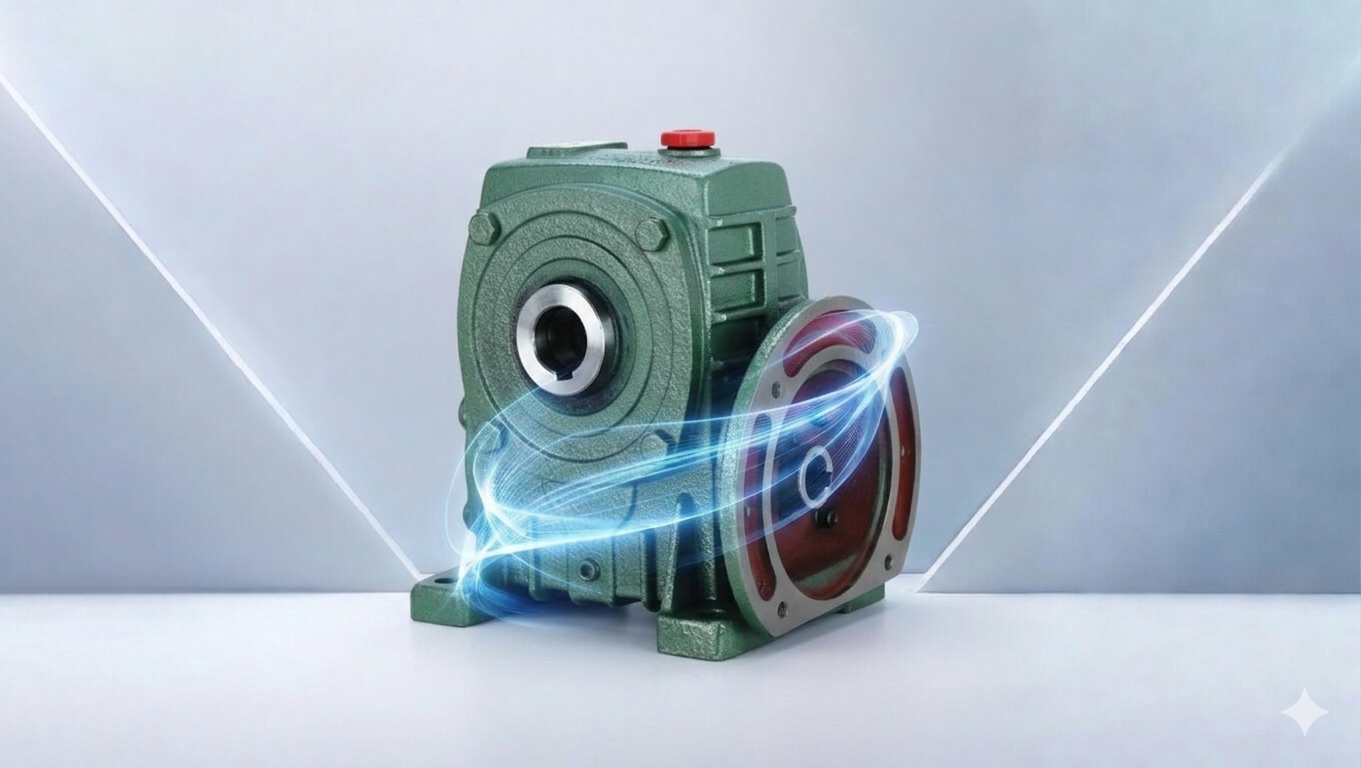
Technical Specifications
Key parameters for CNC feed mechanism and rotary table gearboxes, where dimensional tolerance on the finished workpiece is the ultimate specification constraint.
| Parameter |
Typical Range |
Notes |
| Backlash |
<1 – 5 arc-min |
Must be calculated vs workpiece tolerance at table radius |
| Torsional Stiffness |
Specified in N·m/arc-min |
Load-induced deflection = dimensional error in cut |
| Gear Ratio |
5:1 – 100:1 |
Matched to servo motor speed and table design speed |
| Speed Stability |
±0.1 % at feed rate |
Speed ripple causes surface finish variation |
| Thermal Stability |
Low heat generation |
Thermal growth shifts tool-workpiece datum |
| Positional Repeatability |
±0.001 – ±0.01 mm |
Combined effect of backlash + stiffness + encoder |
CNC Feed Drive Architecture
CNC machine axes use one of two drive architectures, each with a distinct gearbox role. Understanding which architecture is in use on the machine determines the type and performance level of gearbox that is appropriate.
Ball Screw Axis Drives
The dominant CNC feed axis architecture uses a servo motor driving a ball screw through a precision gear reducer. The gear reducer reduces the motor speed to the ball screw rotational speed needed for the required feed rate, and multiplies the motor torque to overcome the cutting force reaction, guide friction, and ball screw preload. The gearbox in this configuration must provide low backlash — the ball screw and nut have their own small axial backlash, and any additional angular backlash in the gearbox is amplified by the screw lead to produce linear axis positioning error. For a 10 mm pitch ball screw, 1 arc-minute of gearbox backlash adds 10 × tan(1/3438) = 0.0029 mm of linear axis uncertainty — approximately 0.003 mm, which is within the 0.01 mm tolerance for medium-precision machining but exceeds the 0.002 mm tolerance for precision toolroom work.
Precision planetary gearboxes (Neugart, Apex Dynamics, Wittenstein Alpha, Shimpo) with 1–5 arc-minute backlash are the standard for ball screw feed axis drives on machining centres and lathes. The gearbox torsional stiffness determines how much the axis position shifts under the varying cutting force — a gearbox that deflects 2 arc-minutes under 100 N·m of cutting torque produces a linear axis error of 100/stiffness × screw_lead / 360° at that torque. Confirm torsional stiffness from the gearbox datasheet and calculate the worst-case loaded position error for the heaviest cutting operation the machine performs.
The inertia ratio between the reflected load inertia (ball screw + table + workpiece, reflected through the gear ratio) and the servo motor rotor inertia determines the servo’s dynamic response. A ratio above 5:1 makes the servo difficult to tune for fast, responsive motion — it responds sluggishly to commanded positions and overshoots or oscillates. The gearbox ratio is a key parameter in managing this inertia ratio: increasing the ratio reduces the reflected load inertia by the ratio squared, at the cost of reduced maximum axis speed.
Rotary Table Drives: Direct Worm or Precision Worm
CNC rotary tables (4th and 5th axis) use a worm and worm wheel drive to rotate the workpiece table through the required angular position. The worm drive is chosen for its ability to achieve high ratios (40:1–180:1) in a compact form while providing the self-locking characteristic that holds the table at any angular position without the motor remaining energised. For standard machining centre rotary tables (Nikken, Tsudakoma, Kitagawa, Yukiwa), the worm gear mesh is precision-ground to achieve backlash below 10 arc-seconds — a much tighter specification than standard industrial worm gearboxes and achievable only through the combination of matched grinding, lapping, and selective assembly.
For trunnion-style 5-axis machining tables where the table tilts as well as rotates, two separate gear drives (one for rotation, one for tilt) must be independently preloaded and adjusted to achieve the combined angular positioning accuracy required. These are purpose-engineered machine tool sub-assemblies from the table manufacturer — the gearboxes are not catalogue industrial items but matched precision components integrated into the machine’s axis design. Replacement requires either the OEM sub-assembly or a specialist precision rebuild of the original unit.
The Backlash-to-Tolerance Calculation: The Starting Point for Every CNC Gearbox
Before selecting a gearbox for any CNC axis, calculate the maximum permissible gearbox backlash from the workpiece tolerance and the machine geometry. This calculation prevents both over-specification (unnecessarily expensive gearbox) and under-specification (gearbox that cannot hold the required tolerance).
Backlash Calculation Example: CNC Rotary Table
Workpiece tolerance: ±0.01 mm positional accuracy at a 100 mm radius from the rotary table centre.
Maximum allowable angular error at table: arctan(0.01 / 100) = 0.00573° = 0.344 arc-minutes.
Gearbox backlash must be below 0.344 arc-minutes — approximately 20 arc-seconds.
This is the sub-arc-minute specification achievable only with a precision worm table or harmonic drive — not a standard industrial worm gearbox at 10–30 arc-minutes. For ±0.05 mm tolerance at 100 mm radius, the limit is 1.7 arc-minutes — achievable with a precision planetary at 1–3 arc-minute class.
Thermal Stability: The Hidden Accuracy Killer
In a precision CNC machine, thermal growth of the gearbox shifts the position of the tool-workpiece datum over the course of the working day. A gearbox that generates 5 W of heat more than its neighbour in an axis drive assembly will expand slightly differently, producing a thermal gradient that shifts the axis’s geometric reference by micrometres per hour. Precision machining centres compensate for spindle thermal growth with real-time thermal compensation models — but gearbox thermal effects in the axis drives are rarely compensated and can accumulate to significant errors over a long machining shift.
Helical planetary gearboxes are preferred over worm gearboxes for CNC axis drives requiring high accuracy, specifically because their 94–97% efficiency generates far less heat than a worm gear at comparable torque. Lower heat generation means smaller thermal gradients, less thermal growth, and better positional repeatability throughout the day. For toolrooms and precision machining operations running 8+ hour shifts, the helical planetary’s thermal stability advantage over a worm equivalent is as important as its backlash specification.
Applications Across Australian Precision Engineering
Aerospace & Defence Manufacturing
Australian aerospace component manufacturers (Boeing Aerostructures, RUAG Australia, GKN Aerospace) and defence manufacturers machining aluminium structures, titanium engine components, and precision gearbox housings use 5-axis machining centres with Nikken, Tsudakoma, or Kitagawa rotary tables at tolerances of ±0.005–0.01 mm. Rotary table precision worm gear replacement and recalibration is a specialist service requiring lapping-matched worm and wheel pairs to restore original accuracy.
Toolmaking & Precision Mould
Toolrooms and precision mould shops across Australia machine hardened steel injection mould cavities, press tools, and jigs to tolerances of ±0.002–0.005 mm. EDM (electrical discharge machining) and jig boring machines require rotary table positioning accuracies of 1–5 arc-seconds, achievable only with direct-drive DDR (direct drive rotary) tables or high-precision worm gear tables from Nikken or Ucam. Gearbox selection for feed axis upgrades on older toolroom machines uses the backlash-to-tolerance calculation as the primary specification driver.
Automotive Component Machining
Engine component machining lines at Australian tier-1 suppliers use transfer machine feed axes and CNC machining centre rotary tables for high-volume production of cylinder heads, brake components, and transmission housings. These require IATF 16949-compliant equipment qualification and capability studies confirming Cpk ≥ 1.33 for the machined feature dimensions — the gearbox backlash and stiffness must be confirmed as contributors to the process capability analysis.
Medical Device Manufacturing
Australian medical device manufacturers machining implants, surgical instruments, and diagnostic equipment housings require sub-0.01 mm dimensional tolerances under TGA and ISO 13485 quality management requirements. Precision planetary or harmonic drive axis gearboxes on 5-axis machining centres enable the combination of tight tolerance and complex geometry needed for implant components. Equipment qualification (IQ/OQ) is required before validated production, including gearbox backlash verification at commissioning.
Sourcing CNC Feed and Rotary Table Gearboxes in Australia
CNC feed and rotary table gearbox specifications must include: backlash (arc-minutes) with the test torque and temperature at which it was measured; torsional stiffness (N·m/arc-minute); gear ratio; peak and rated torque; reflected inertia; motor flange standard (IEC or NEMA); maximum input speed; thermal power rating at the machine’s ambient temperature; and for rotary tables, the self-locking torque margin at rated holding load. For precision bevel gear stages in CNC axis angular drive elements, providing accurate bevel gear load and dimensional specifications ensures correct mesh rating for the combined cutting force and servo dynamic loads. We supply precision planetary gearboxes and CNC-grade worm drives for machining centre feed axis and rotary table applications across Australia. Browse on our CNC feed and rotary table drive solutions page, or contact our engineering team for a specification within one business day.
Frequently Asked Questions
Practical answers for CNC machine designers, toolroom engineers, and precision manufacturing specialists selecting gearboxes for machine tool feed axes.
1. How do I calculate the maximum gearbox backlash for my rotary table application?
+
Maximum gearbox backlash = arctan(workpiece positional tolerance / table radius from axis centre). Convert the result from degrees to arc-minutes (multiply by 60). For ±0.02 mm tolerance at 80 mm radius: arctan(0.02/80) = 0.01432° = 0.859 arc-minutes. The gearbox backlash must be below this value. Important note: the workpiece tolerance must be halved if it is a bilateral tolerance (± means total range is 2× the stated value) and the backlash specification must cover the full total range — a ±0.02 mm tolerance means any point must be within 0.02 mm of nominal, and the backlash must produce less than 0.02 mm uncertainty in either direction from the commanded position. Always confirm whether your tolerance is the total band or the ± value; the distinction halves or doubles the permissible backlash.
2. What inertia ratio should I target for a CNC servo axis gearbox?
+
The load inertia reflected to the servo motor input should be between 1:1 and 5:1 relative to the motor rotor inertia for most CNC servo applications. Below 1:1, the motor response is sluggish (insufficient load inertia for smooth motion); above 5:1, the servo struggles to accelerate and decelerate the load without oscillation or position overshoot. Reflected load inertia = (J_screw + J_table_at_output) / gear_ratio². The gear ratio squared in the denominator means increasing the ratio dramatically reduces the reflected inertia: doubling the ratio reduces reflected inertia by 4×. For a heavy rotary table axis where the natural inertia ratio is 20:1, increasing the gear ratio from 5:1 to 10:1 reduces the ratio from 20:1 to 5:1 — a significant improvement in servo dynamic response at the cost of a lower maximum table speed.
3. Why does my CNC rotary table accuracy degrade over the working day?
+
Accuracy degradation over the working day is a thermal drift signature. As the rotary table gearbox warms from ambient to operating temperature, the worm gear mesh clearances change (thermal expansion), the lubrication viscosity drops, and the preload in the precision bearings shifts slightly. These effects together change the effective backlash and the elastic deflection under cutting load — typically by 2–5 arc-seconds over the first 30–60 minutes of operation as the table reaches thermal equilibrium. The standard solution is a warm-up routine — cycling the table through its full travel range for 20–30 minutes before the first measurement cut — to stabilise the thermal state before beginning critical work. If the drift continues beyond 60 minutes, check the gearbox oil fill level and confirm the ambient temperature is within the gearbox’s rated range.
4. How does torsional stiffness affect surface finish quality on a CNC lathe?
+
On a CNC lathe, the cutting force varies continuously as the tool engages and disengages at the workpiece surface. Each force variation causes the axis gearbox to deflect slightly if its torsional stiffness is insufficient. This periodic deflection appears as a waviness in the machined surface — the surface finish Ra value includes a periodic component at the frequency of the force variation. For turning, this appears as a fine spiral on the machined surface. For milling, it appears as a regular pattern of ridges at the tooth engagement frequency. Increasing gearbox torsional stiffness (N·m/arc-minute) reduces the amplitude of this deflection at each cutting force cycle, directly improving surface finish. A helical planetary gearbox with torsional stiffness 3–5× higher than the previous worm drive on the same axis will produce a measurably better surface Ra if the deflection from the worm drive was the dominant surface roughness contributor.
5. What documentation should a CNC precision gearbox supplier provide?
+
For CNC feed and rotary table gearboxes: backlash measured at the stated test torque and temperature (not just the catalogue nominal); torsional stiffness curve (torque vs angular deflection); peak and rated output torque; gear ratio with tolerance; reflected inertia to motor input; thermal power rating at operating ambient; motor flange drawing (confirming pilot diameter, bolt circle, and register dimensions match the servo motor); IOM manual with preload adjustment procedure (for adjustable-backlash worm tables) and lubrication schedule; and for aerospace and medical applications, material test certificates for gear and shaft materials. Request the backlash measurement certificate as a separate document, not just the catalogue specification — some suppliers’ catalogue backlash values are nominal design values, not 100% tested values, and the actual unit may exceed the nominal.
Get CNC Axis Gearboxes Specified to Your Workpiece Tolerance
Share your workpiece tolerance, table radius, servo motor specification, and cutting load — our engineers will return a specification with backlash budget calculation and torsional stiffness verification within one business day.
Request a Free CNC Gearbox Specification →
