Gantry Robot & Pick-and-Place Drive Systems · Industrial Gearbox Engineering · Australia
Technical Application Reference
Gantry robots and pick-and-place systems operate at the intersection of precision and speed — two properties that pull gearbox specifications in opposite directions. A gantry robot picking 120 parts per minute must accelerate, traverse, decelerate, and position within ±0.5 mm in less than 0.5 seconds. The gear motor driving each axis must provide high acceleration torque, smooth velocity during traverse, and precise deceleration to the pick or place position — all at high cycle rates that accumulate to tens of millions of direction reversals per year. This guide covers the engineering basis for gantry robot and pick-and-place drive gearbox selection across Australian packaging, electronics, and assembly automation operations.
X-Y-Z Axis & Rack-and-Pinion Drives
High-Cycle Bearing Life & RMS Torque
Packaging, Electronics & Assembly Automation
Technical Specifications
Key parameters for gearboxes in gantry robot and pick-and-place applications, where cycle rate, acceleration performance, and bearing fatigue life are specified alongside the standard accuracy and torque requirements.
| Parameter |
Typical Range |
Notes |
| Cycle Rate |
20 – 200+ picks/min |
Delta robots at upper end; gantries typically lower |
| Positioning Accuracy |
±0.05 – ±1 mm |
Electronics pick-and-place tighter than packaging |
| Backlash |
3 – 10 arc-min |
Encoder feedback compensates; lower is still better |
| Bearing Cycle Count |
10–100 million rev/yr |
Must confirm L10 life vs machine design life |
| RMS Torque |
From duty cycle calculation |
Peak accel torque × sqrt(duty fraction) |
| IP Rating |
IP54 – IP65 |
Food and pharma lines need IP65 |
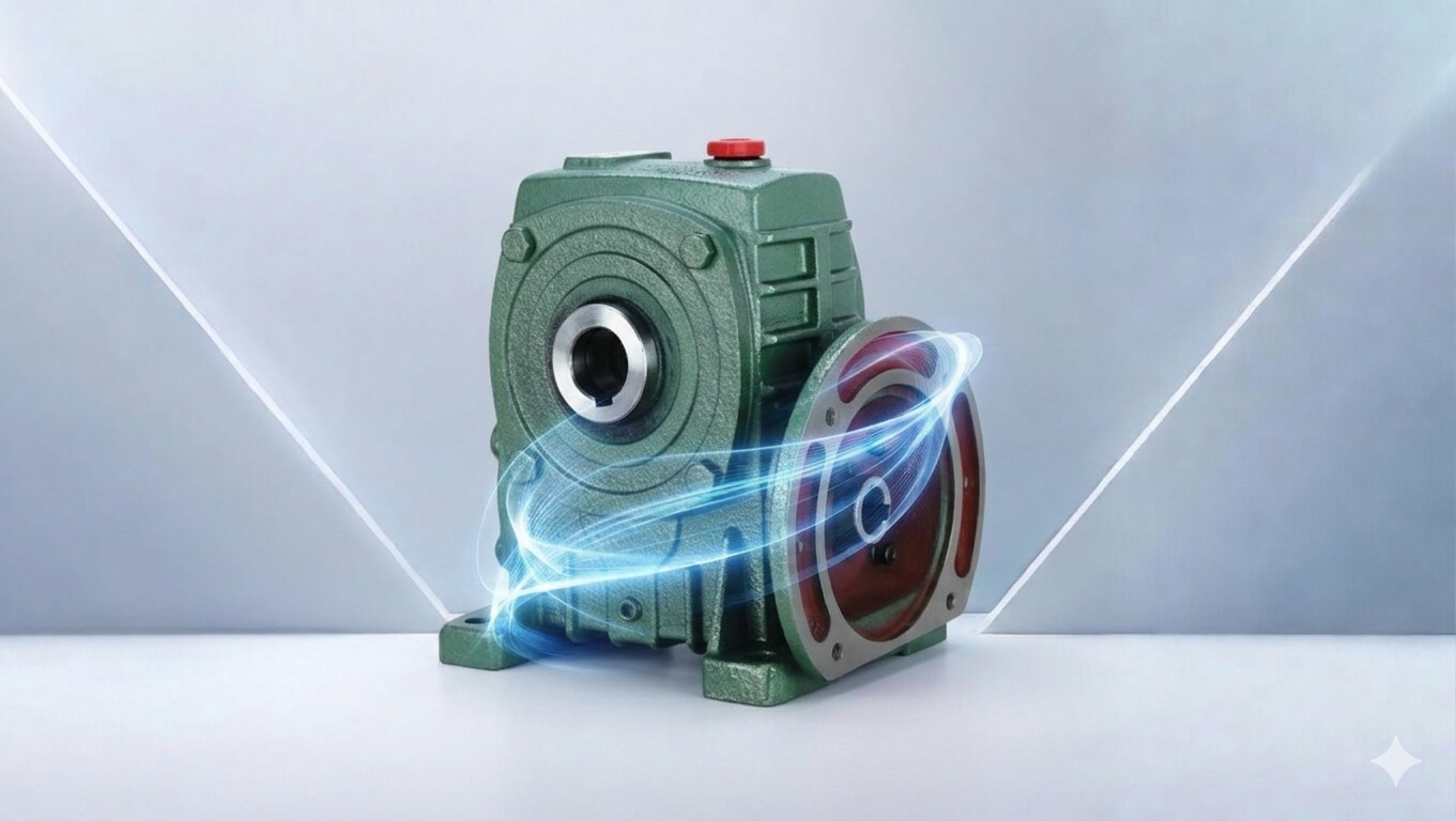
Gantry Robot Drive Architecture
Gantry robots use Cartesian (X-Y-Z) motion, with each linear axis driven by a servo motor through a gear reducer and either a ball screw (shorter strokes, higher force) or a rack-and-pinion drive (longer strokes, higher speed). The gearbox is the critical interface element connecting servo motor to the motion mechanism.
Rack-and-Pinion Gantry Drives
Long-travel gantry axes (1–10 metres or more) use rack-and-pinion drives where a precision planetary gearbox drives a pinion that meshes with a rack mounted along the travel path. The rack-and-pinion replaces the ball screw for long strokes because it is not limited by critical speed (the ball screw’s rotational speed limit) and can be extended to any length by adding rack sections. The gearbox backlash appears directly as positioning uncertainty at the pinion-rack interface: backlash × pinion pitch radius (in mm) = linear positioning uncertainty. For a 20 mm PCD pinion, 5 arc-minutes of backlash = 0.029 mm of linear positioning uncertainty — acceptable for most packaging and general assembly gantries with ±0.1–0.5 mm accuracy requirements.
Dual-drive gantry axes (two servo motors and gearboxes driving opposite ends of a bridge carriage) require accurate synchronisation to prevent the bridge from racking (skewing relative to the linear guides). Electronic cross-coupling control compares encoder feedback from both ends and corrects any position differential within the servo control loop. The gearbox backlash on each drive must be matched within 2–3 arc-minutes to keep the synchronisation error within the control system’s correction bandwidth at full traverse speed. Precision planetary gearboxes from Neugart, Apex Dynamics, or Wittenstein with confirmed matched backlash pairs are the standard for dual-drive gantry axes.
Delta and Parallel Kinematics Pick-and-Place
Delta robots (Fanuc M-1iA, ABB FlexPicker, Adept Quattro, OMRON Quattro) use three rotary arms driven in parallel to position the end-effector in X-Y-Z space. Each arm is driven by a servo motor through a precision gearbox — typically a precision planetary unit mounted directly to the arm pivot shaft. Delta robots achieve 200–400 picks per minute and cycle continuously for years. The bearing cycle count at these rates is the dominant service life driver — for 300 picks per minute × 60 minutes × 16 hours × 300 days per year, each arm gearbox executes 86 million direction reversals per year. Bearing L10 life calculated at the RMS radial load and this cycle frequency must confirm the gearbox service life exceeds the machine design life (typically 10 years) before selection is finalised.
RMS Torque and Bearing Life: The Two Critical Sizing Calculations
Unlike a continuous-duty industrial drive, pick-and-place and gantry gearboxes operate in a highly repetitive intermittent duty cycle. Two calculations — RMS torque and bearing cycle count — determine whether the gearbox will survive its design life, and both must be performed before selection is finalised.
RMS Torque: Thermal Sizing
RMS torque = √[(T²_accel×t_accel + T²_traverse×t_traverse + T²_decel×t_decel) / (t_accel + t_traverse + t_decel + t_dwell)]. For a 0.4 s pick cycle with 0.08 s acceleration at 80 N·m, 0.12 s traverse at 15 N·m, 0.08 s deceleration at 60 N·m, and 0.12 s dwell: RMS = √[(6,400×0.08 + 225×0.12 + 3,600×0.08) / 0.4] = √2,039 = 45 N·m. The gearbox continuous thermal rating must exceed 45 N·m, even though the peak acceleration torque is 80 N·m.
Thermal rating must exceed RMS · Not peak
Bearing Cycle Count: Fatigue Sizing
Annual reversals = picks/minute × 60 × hours/day × days/year × reversals/pick. For 100 picks/minute, 16 hours/day, 300 days/year, 2 reversals per pick: 100 × 60 × 16 × 300 × 2 = 576 million reversals/year. For a 10-year machine life: 5.76 billion reversals. Bearing L10 = (C/P)³ × 10⁶ for ball bearings — confirm C/P ratio yields L10 above 5.76 billion at the operating radial load P. This calculation must be requested from the gearbox supplier as a deliverable.
L10 must exceed machine life × annual cycles
Applications Across Australian Automation Industries
Food & Beverage Packaging
Delta and SCARA robots handling biscuits, confectionery, and fresh produce on Australian packaging lines operate at 60–200 picks per minute in food contact zones. IP65 gear motors with NSF H1 lubricants and smooth external profiles are required in the product zone. Bearing cycle count confirmation for the 10-year machine design life is a procurement requirement at major FMCG producers that amortise robot capital cost over the full design life.
Electronics Assembly
PCB component placement machines, wafer handling gantries, and connector assembly systems in Australian electronics manufacturing operate at the tightest positioning accuracy in the pick-and-place category — ±0.05 mm or better. Precision planetary gearboxes with backlash below 3 arc-minutes and high torsional stiffness are required to achieve this accuracy at the high speeds needed for competitive cycle rates. ESD-grounded gearbox mounting is required in semiconductor and sensitive electronics environments.
Automotive Assembly
Gantry robots at automotive assembly suppliers handling engine components, body fasteners, and sub-assemblies use rack-and-pinion long-travel axes with precision planetary gearboxes. IATF 16949 equipment management requires documented capability studies confirming the gearbox’s contribution to assembly positional accuracy, with periodic re-verification confirming that backlash has not grown beyond the process capability limit.
E-Commerce Fulfilment
Goods-to-person and item-picking gantry systems at Australian e-commerce fulfilment centres (Amazon, Catch, Australia Post) handle diverse SKU ranges at 20–60 picks per minute with positioning accuracy of ±0.5–2 mm. The gantry spans may extend to 8–12 metres, requiring long-rack rack-and-pinion drives with dual-axis synchronisation. Standardisation on a single gearbox model across all axes simplifies the spare parts inventory for the facility’s maintenance team.
Sourcing Gantry Robot and Pick-and-Place Gearboxes
Gantry and pick-and-place gearbox specifications must include: RMS torque at the actual cycle rate (not peak acceleration torque); bearing L10 life at cycle rate and machine design life; backlash at stated test torque; torsional stiffness; motor flange standard; gear ratio with inertia ratio verification; IP rating with food-zone lubricant type if applicable; and for rack-and-pinion drives, the pinion pitch radius to confirm linear positioning accuracy from gearbox backlash. For gantry axes incorporating bevel gear angle changes in the drive train, providing complete shaft coupling dimensional and fit tolerance data for both the motor side and rack-drive side ensures correct assembly without field machining. We supply precision planetary gearboxes for gantry robot and pick-and-place applications across Australia. Browse on our gantry and pick-and-place drive solutions page, or contact our engineering team for a specification within one business day.
Frequently Asked Questions
Common questions from automation engineers and system integrators specifying gearboxes for gantry robots and pick-and-place systems.
1. Why does a gantry robot overrun its target position at high speeds?
+
Position overshoot at high speeds indicates either an inertia ratio problem or a torsional compliance problem. If the inertia ratio (reflected load to motor rotor) is above 5–10:1, the servo cannot decelerate the load quickly enough to stop precisely at the target — the motor de-energises correctly but the load’s kinetic energy carries it past the stop point. Solution: increase gear ratio to reduce reflected inertia, or reduce traverse speed to reduce kinetic energy at the deceleration point. If the inertia ratio is within range but overshoot still occurs, the gearbox torsional compliance is allowing the load to coast past the point where the motor encoder says it has stopped — the gearbox is twisting slightly during deceleration and releasing the stored energy after the motor stops. This is diagnosed by encoder position vs position feedback disagreeing at the overshoot moment. Solution: increase gearbox torsional stiffness or reduce peak deceleration rate.
2. How does rack-and-pinion backlash affect the positioning accuracy of a long-travel gantry?
+
For a rack-and-pinion drive, linear backlash = gearbox backlash (radians) × pinion pitch circle radius. For a 5 arc-minute gearbox with a 20 mm PCD pinion (10 mm pitch radius): linear backlash = (5/3,438) × 10 = 0.0146 mm — approximately ±0.015 mm of linear positioning uncertainty at every direction reversal. This is the contribution from the gearbox alone; the rack-pinion mesh itself adds another 0.01–0.02 mm typically. Combined backlash of 0.02–0.04 mm is well within the ±0.1–0.5 mm accuracy of most gantry applications, and the servo controller compensates for a significant portion of this through its following error correction. If positioning accuracy degrades beyond the commissioning baseline, measure the actual backlash at the pinion (torque the pinion in both directions with no motor current and measure the angular play) and compare to the original specification.
3. What maintenance does a high-cycle pick-and-place gearbox need?
+
For a precision planetary gearbox on a 100 picks/minute delta or SCARA robot: annual backlash measurement compared to commissioning baseline (using a torque wrench at the output shaft in both directions and measuring angular play); grease renewal at 5,000 operating hours for grease-lubricated units (confirm with the manufacturer — some high-cycle units specify shorter intervals); vibration trending from the servo drive’s current monitoring (increasing bearing noise appears as current ripple that the servo drive can detect before it is audible); and bearing replacement at the L10 life interval calculated at commissioning. For food zone gantries: additionally inspect gearbox external sealing for any cracks or gaps that could allow food product or cleaning chemical to enter; re-grease any exposed output shaft seal at every annual service.
4. What documentation should a gantry robot gearbox supplier provide?
+
For gantry and pick-and-place gearboxes: backlash (arc-minutes, at test torque and temperature); torsional stiffness; peak and rated output torque; RMS torque rating at the application cycle rate; bearing L10 life calculation at cycle rate and machine design life; gear ratio; reflected inertia; motor flange drawing; IOM manual with grease renewal interval and backlash check procedure; for rack-and-pinion applications, the permissible pinion radial load capacity and the recommended rack module; and for dual-drive synchronised gantries, the matched backlash tolerance for paired units (confirm units from the same production batch can be matched within ±1 arc-minute). Request these documents before placing the order — the L10 life calculation in particular must be performed with the actual application load, not the catalogue rated load, to confirm the bearing adequately covers the machine’s design life at the customer’s cycle rate.
Get Gantry and Pick-and-Place Gearboxes Specified for Your Cycle Rate and Accuracy
Share your picks per minute, axis stroke, payload, positioning accuracy, and machine design life — our engineers will return a specification with RMS torque, bearing L10 life, and inertia ratio confirmation within one business day.
Request a Free Gantry Robot Gearbox Specification →
