Description
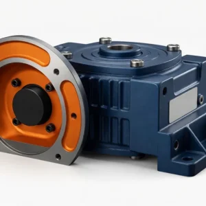
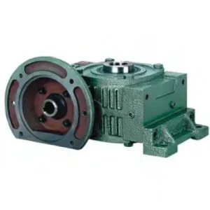
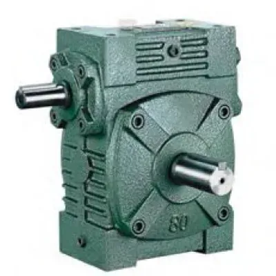
Before the WP family established the IEC-standardised dimensional convention now dominant in Australian industrial drives, the W Series worm gear reducer defined the dimensional footprint that generations of Australian plant engineers designed machinery around. The W series follows its own proven dimensional convention — taller housing profile relative to centre distance, a through-shaft input that accepts drive from either side of the worm shaft, a broad output shaft section, and a size range from 40 through 200 that covers input powers from fractional-kilowatt indexing drives to continuous-duty material handling applications. For Australian manufacturers in Sydney, Melbourne, Brisbane, Perth, and Adelaide who are replacing worn-out W series units in legacy machinery — or who specify W series for its larger output shaft section, through-shaft input flexibility, or simple foot-mount format in applications not requiring IEC-specific motor flanges — the W series remains a technically sound, actively stocked product. Manufactured to ISO 9001:2015, designed per AGMA 6034, and supplied by Ever-Power Worm Gear Reducer Co., Ltd. (Australia), 27 Harley Crescent, Condell Park NSW 2200.
Key Specifications & Parameters — W Series Worm Gear Reducer
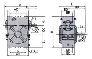
All sizes and dimensions per ISO 9001:2015 and AGMA 6034. Input shaft extends from both sides of the housing (through-shaft). Output shaft is solid, single side.
| Size | Ratio Range | Centre Dist. A (mm) | Overall Length B (mm) | Height H (mm) | Input Shaft Extension HL (mm) | Input Shaft Ø HS (mm) | Output Shaft Ø (mm) | Weight (kg) |
|---|---|---|---|---|---|---|---|---|
| 40 | 10:1–60:1 | 148 | 122 | 125 | 35 | 25 | 28 | 14 |
| 50 | 10:1–60:1 | 175 | 145 | 150 | 35 | 30 | 40 | 17 |
| 60 | 10:1–60:1 | 195 | 165 | 177 | 42 | 40 | 50 | 22 |
| 70 | 10:1–60:1 | 234 | 195 | 215 | 55 | 40 | 60 | 28 |
| 80 | 10:1–60:1 | 264 | 210 | 250 | 65 | 50 | 65 | 32 |
| 100 | 10:1–60:1 | 322 | 245 | 310 | 80 | 50 | 75 | 38 |
| 120 | 10:1–60:1 | 385 | 285 | 370 | 95 | 65 | 85 | 45 |
| 135 | 10:1–60:1 | 435 | 320 | 425 | 105 | 75 | 95 | 55 |
| 155 | 10:1–60:1 | 494 | 387 | 461 | 103 | 85 | 110 | 60 |
| 175 | 10:1–60:1 | 548 | 407 | 521 | 123 | 85 | 110 | 65 |
| 200 | 10:1–60:1 | 688 | 480 | 575 | 130 | 95 | 125 | 70 |
What Is the W Series Worm Gear Reducer and Its Through-Shaft Input?

The W series is the predecessor family to the WP series. While the WP family adopted IEC-standardised mounting dimensions for compatibility with European-specification motors and machines, the W series followed its own dimensional convention developed through decades of Australian and Asian industrial machinery practice. The key distinguishing features of the W series compared with the WP family are:
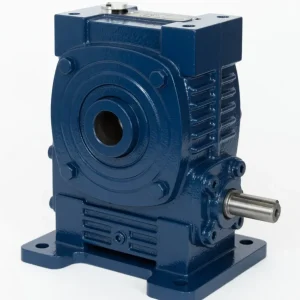
- Through-Shaft Input (Both Sides): Unlike WP units where only one side of the worm shaft extends from the housing, the W series worm shaft extends from both sides of the housing as standard — creating two usable input shaft stubs without any additional modification. This through-shaft arrangement is particularly valued in applications where the motor must approach from a specific direction dictated by machine geometry, or where a secondary input device (encoder, hand-wheel, electromagnetic brake) must mount on the opposite side from the primary motor. In the W series, this dual-access is the standard configuration rather than a special “D” variant as in the WP family.
- Taller Housing Profile: The W series housing is proportionally taller relative to centre distance than the WP series — the height-to-centre-distance ratio is approximately 0.85:1 in the W series versus 0.75:1 in the WP series. This taller profile results from the deeper output shaft section and the wider bearing span, both of which provide the W series with a higher overhung load capacity at the same centre distance compared with the WPA.
- Larger Output Shaft Diameter: At each frame size, the W series output shaft diameter is larger than the equivalent WPA — for example, W series size 100 has a Ø75 mm output shaft versus the WPA’s standard output shaft at the same centre distance. This larger shaft diameter provides higher torque capacity per unit shaft cross-section and better resistance to torsional fatigue under cyclic loads.
- Size Range to 200: The W series extends to size 200 (688 mm centre distance, Ø125 mm output shaft, 70 kg) — well beyond the WPA’s maximum size 155. At size 200, the W series provides output torques approaching 20,000 N·m at 60:1, making it suitable for large-scale industrial material handling, heavy gate drives, and large-diameter rotary equipment in Australian mining and infrastructure projects.
W Series vs WP Series — Understanding the Key Differences
| Feature | W Series | WP Series (WPA/WPS) |
|---|---|---|
| Input shaft access | Both sides standard (through-shaft) | Single side (dual requires WPDA/WPDKS variant) |
| Dimensional standard | W series convention (taller H, larger HS) | IEC/AGMA standard (interchangeable with European brands) |
| Size range | 40 – 200 | 40 – 250 (WPS) |
| Output shaft Ø (size 100) | Ø75 mm | Ø75 mm (WPS-class) |
| Motor connection | Via flexible coupling to shaft stub | Coupling or IEC flange (D variant) |
| Interchange with legacy W machines | Direct replacement | May require adaptor for non-IEC machines |
| Best for | Legacy replacement, through-shaft input, size 200 | New machine design, IEC motor direct mount |
Manufacturing Quality and Material Specification — W Series
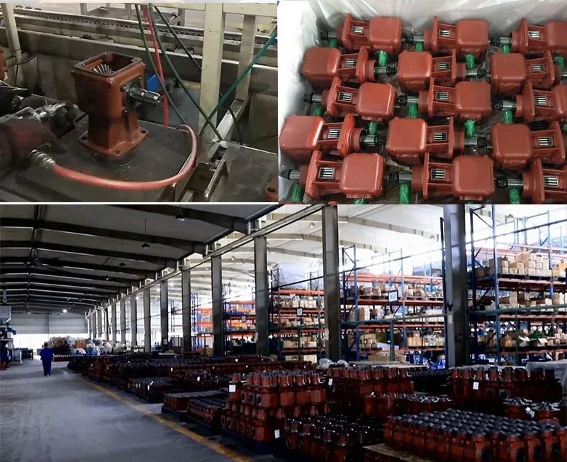
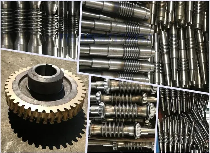
The W series is produced to the same ISO 9001:2015 quality management system and material specifications as the WP family, ensuring consistency across the full Ever-Power worm reducer range:
- Housing: GG25 grey cast iron, machined bearing bores to H7 tolerance, all mating faces to flatness 0.02 mm/100 mm. Zinc-phosphate primed, epoxy topcoat for corrosion resistance in Australian coastal and industrial environments.
- Worm Shaft: 20CrMnTi alloy steel, carburised and quenched to HRC 56–62, thread flanks precision-ground to DIN 3975 Class 8 accuracy with surface roughness Ra ≤ 0.8 μm — the threshold for full hydrodynamic film formation in the worm-bronze mesh.
- Worm Wheel: ZCuSn10Pb1 tin-bronze, hobbed to conjugate geometry matched to the specific worm profile, providing the 5:1 hardness ratio between worm and wheel required by AGMA 6034 for optimal bronze gear wear life.
- Output Shaft: 45# chromium steel, h6 tolerance per DIN 748, DIN 6885 keyway dimensions — compatible with standard Australian market keyways and coupling hubs.
- Input Shaft (Through-Shaft): The input shaft extends from both sides of the housing in symmetrical stub lengths. Both stubs are identical in diameter and keyway, allowing motor coupling from either side without modification. The unused stub accepts a cover plate or is guarded per AS 4024 machinery guarding requirements.
How to Select the Right W Series Frame Size
- Identify Input Side: The W series through-shaft allows motor coupling from left or right. Determine from machine layout which side the motor must approach from. Both stubs are identical — no model variant needed for left versus right hand input.
- Calculate Design Torque with Service Factor: T_design = (Motor kW × 9,550 / Output rpm) × SF. Apply SF 1.25 for smooth loads, SF 1.5 for moderate shock, SF 2.0 for heavy shock. Select the smallest W series frame whose rated output torque at your ratio ≥ T_design.
- Legacy Replacement Check: If replacing an existing W series unit, confirm the frame size from the existing unit’s nameplate (size number = centre distance in mm, e.g., W100 = 100 mm centre distance). The W series dimensions are consistent across manufacturers following the W series convention — Ever-Power W series should be a direct replacement at the same size.
- Self-Locking: The W series worm mesh is self-locking at ratios 20:1 and above. Confirm ratio selection accordingly for gravity-loaded applications.
- Guard the Unused Input Stub: The unused through-shaft stub must be guarded per AS 4024.1 (Australian Standard for machinery safeguarding) when the machine is in operation. A stub shaft cover plate (available from Ever-Power as a stocked accessory) bolts over the unused stub and provides the required guarding.
Accessories We Also Supply: Input stub shaft cover plates, flexible jaw and disc couplings for W series shaft diameters, output sprockets (pilot bore and finished bore), replacement oil seals, and hand-wheel assemblies for secondary input stub. Contact Ever-Power Australia for pricing.
W Series Applications in Australian Industry — Legacy and New-Build
The W series serves two distinct roles in the Australian market: as a replacement part for legacy machinery built around the W dimensional convention, and as a new-specification choice in applications where the through-shaft input geometry is an engineering advantage:
| Application Type | Location | W Series Advantage |
|---|---|---|
| Legacy machine replacement | All Australian states | Direct dimensional interchange with existing W series units |
| Conveyor drives with encoder feedback | Sydney, Melbourne, Brisbane | Encoder mounts on unused input stub — no separate encoder bracket |
| Gate/valve drives needing manual override | Perth, Adelaide, Brisbane | Hand-wheel on unused input stub — no secondary reducer needed |
| Rotary drum and large material handling (size 200) | WA mining, QLD processing | Size 200 provides highest torque in W family — beyond WPA maximum |
| Tandem/cascade two-motor drives | Melbourne, Sydney | Both motor stubs accessible without reducer modification |

What Australian Customers Say About the W Series
“Our Sydney food processing line has 28 W100 units that we’ve maintained for 15 years. Ever-Power W series is the first direct replacement we’ve found — identical dimensions, mounting bolt pattern, shaft diameters. No machine modifications needed. Supply is reliable and pricing is significantly better than our previous supplier.”
— Brian K., Maintenance Manager, Sydney NSW
“We specified W80 units for our Brisbane conveyor drive with encoder feedback. The through-shaft means the encoder mounts directly on the unused input stub — no adaptor bracket, no separate mounting. The worm shaft is the encoder shaft. Simple, reliable, zero extra hardware.”
— Nicole F., Automation Engineer, Brisbane QLD
“W120 on our irrigation gate drive in SA — the hand-wheel on the unused stub allows manual operation during power outages and the self-locking at 40:1 holds the gate position without power. 4 stars because the through-stub cover plate is an add-on purchase rather than included — minor point.”
— Fred N., Irrigation Manager, Riverland SA
“Replaced W200 units on our WA mineral processing rotary drum drives. The size 200 is the largest W series unit available and it’s exactly what we needed for the shaft torque. Ever-Power had them in stock — lead time was 10 days to Perth, which surprised us for units of that size.”
— Gary T., Site Engineer, Kalgoorlie WA
Why Choose Ever-Power for W Series Worm Reducers in Australia?
Ever-Power Worm Gear Reducer Co., Ltd. (Australia) at 27 Harley Crescent, Condell Park NSW 2200 maintains stock of W series units across all eleven frame sizes for fast 5–10 business day dispatch. Our engineering team provides free legacy interchange checks and dimensional confirmation before you order. Visit About Us for our full capabilities. Technical documentation at worm-gearbox.top.