Description
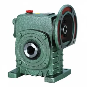
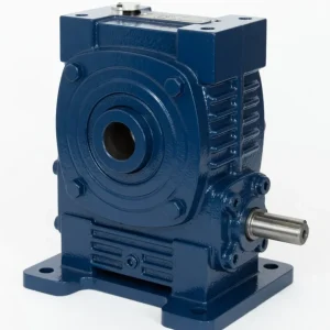
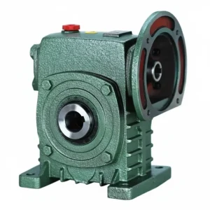
The WA & WS Series worm gear reducer combines the W family’s signature through-shaft input — accessible from both sides of the housing as standard — with a hollow bore output that mounts directly onto the driven machine shaft, eliminating the output coupling. The WA provides the standard WPA-class bore depth suitable for light-to-medium shaft engagement requirements, while the WS delivers the deeper WPS-class bore engagement, longer key contact area, and higher overhung load capacity needed for heavy-duty chain and belt drive applications. Together, this pair covers shaft-mount drive requirements across the full W series size range from 40 to 200 — from small indexing drives at size 40 up to heavy material handling at size 200 — all within the W series dimensional convention that legacy Australian machinery was originally engineered around. For Australian manufacturers in Sydney, Melbourne, Brisbane, Adelaide, and Perth who need to replace worn hollow-bore W series units in legacy equipment, or who are specifying new drives where the through-shaft input geometry and hollow bore output are both required in the W series dimensional footprint, the WA & WS are the definitive solution. Manufactured to ISO 9001:2015, designed per AGMA 6034, and supplied by Ever-Power Worm Gear Reducer Co., Ltd. (Australia), 27 Harley Crescent, Condell Park NSW 2200.
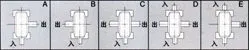
Key Specifications & Parameters — WA & WS Series Worm Gear Reducer
WS Series — WPS-Class Bore Depth
Deeper bore engagement (HL-WS), longer key contact area, higher overhung load. Through-shaft input both sides. Preferred for chain/belt loaded outputs and shock applications in W series machines.
WA Series — WPA-Class Bore Depth
Standard bore engagement (HL-WA), lighter bearing arrangement. Through-shaft input both sides. Suitable for smooth continuous loads in legacy W series equipment across all frame sizes 40–200.
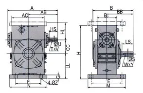
| Size | Ratio | A (mm) | B (mm) | H (mm) | HL-WS (mm) | HL-WA (mm) | Output Bore Ø (mm) | Weight (kg) |
|---|---|---|---|---|---|---|---|---|
| 40 | 10:1–60:1 | 148 | 122 | 135 | 60 | 45 | Ø14 | 4 |
| 50 | 10:1–60:1 | 175 | 145 | 165 | 80 | 50 | Ø17 | 7 |
| 60 | 10:1–60:1 | 195 | 165 | 195 | 93 | 60 | Ø22 | 11 |
| 70 | 10:1–60:1 | 234 | 195 | 233 | 108 | 73 | Ø28 | 15 |
| 80 | 10:1–60:1 | 264 | 210 | 268 | 123 | 83 | Ø32 | 23 |
| 100 | 10:1–60:1 | 322 | 245 | 330 | 150 | 100 | Ø38 | 38 |
| 120 | 10:1–60:1 | 385 | 285 | 395 | 180 | 120 | Ø45 | 65 |
| 135 | 10:1–60:1 | 435 | 320 | 455 | 215 | 135 | Ø55 | 84 |
| 155 | 10:1–60:1 | 494 | 387 | 493 | 235 | 135 | Ø60 | 114 |
| 175 | 10:1–60:1 | 548 | 407 | 558 | 260 | 160 | Ø65 | 150 |
| 200 | 10:1–60:1 | 688 | 480 | 620 | 290 | 175 | Ø70 | 218 |
Green HL-WS = WS (deep bore, WPS-class) depth. Amber HL-WA = WA (standard bore, WPA-class) depth. Output bore Ø is shared across both WA and WS — only depth differs.
What Are the WA and WS Series — Through-Shaft Input Meets Hollow Bore Output
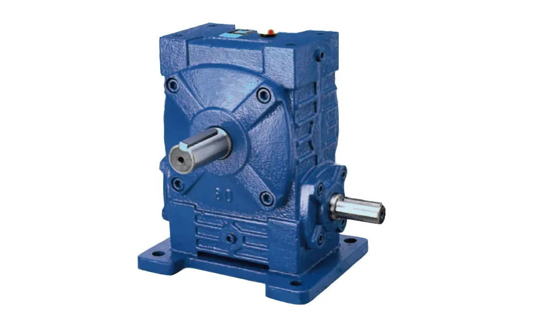
The WA and WS series represent the hollow-bore output members of the W family, maintaining the W series’ characteristic through-shaft input while replacing the solid output shaft stub with a keyed bore that mounts directly onto the driven shaft — eliminating the output coupling that conventional W series solid-shaft units require.
The critical distinction between WA and WS lies entirely in the bore depth (HL) at each frame size. The WA uses the WPA-class bore depth — the same HL as the WPKA at equivalent centre distances — providing adequate engagement for smooth continuous loads on shafts that are short or that do not experience cyclic shock. The WS uses the WPS-class bore depth — the same deeper HL as the WPKS — providing the greater key contact area, higher bore engagement torque capacity, and better shock resistance needed for chain conveyor head shafts, auger drives, and impact-loaded applications in Australian mining and agricultural operations.
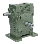
The through-shaft input of both WA and WS — inherited from the base W series — extends from both housing faces as standard. This means that on a WA or WS, the installer can connect the motor from either side without any modification to the reducer, a property unique to the W family that the WP family achieves only in dedicated dual-input variants. The same AS 4024-compliant stub cover plate must be fitted to the unused input stub on both WA and WS units during operation.
WA vs WS — Selection Decision Guide
| Application Condition | Specify WA | Specify WS |
|---|---|---|
| Load type | Smooth continuous (conveyor, mixer, agitator) | Shock, reversing, cyclic (chain, auger, crusher feeder) |
| Service factor | SF ≤ 1.25 | SF ≥ 1.5 |
| Bore engagement length required | ≤ HL-WA (see table above) | > HL-WA or full deep engagement preferred |
| Input power at size 80+ | ≤ 0.75 kW | ≥ 1.1 kW (tapered roller benefits become relevant) |
| Legacy machine replacement | Replacing existing WA unit | Replacing existing WS unit or upgrading WA |
| Unit cost | Lower | 8–12% higher at same frame |
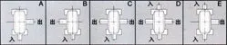
How to Select and Install the WA or WS Worm Gear Reducer
Selection:
- WA or WS: Use the decision guide table above. When in doubt for a new design, specify WS — the additional bore depth and bearing capacity improve reliability at modest additional cost.
- Frame Size and Torque: WA rated output torques equal the WPA (W family convention) at each frame; WS rated torques equal the WPS convention. Apply service factor and confirm rated torque adequacy.
- Bore Diameter: Confirm driven shaft diameter matches the standard bore at your chosen frame (see table). Non-standard bore diameters available on 2–3 week custom order.
- Engagement Length: Confirm driven shaft extends into the bore by at least 1.2 × bore diameter. For WA, verify shaft length ≤ HL-WA. For WS, verify shaft length ≤ HL-WS. If shaft engagement requirement exceeds even the HL-WS, contact Ever-Power for a custom deep-bore variant.
- Input Side Selection: Identify from machine layout which side the motor will enter from. Both sides are identical — no special ordering variant is needed. Order the standard WA or WS and specify motor input side in the delivery notes for correct oil port location in your mounting orientation.
Installation:
- Mount onto Driven Shaft: Clean shaft, apply anti-fretting compound. Slide WA/WS bore over shaft with key aligned. Torque setscrews to specification. Fix torque arm to machine frame with 3–5 mm free movement at pivot pin.
- Connect Motor via Coupling: Align motor coupling to through-shaft stub per normal coupling alignment procedure. For W series input shaft diameters, standard jaw couplings (insert sizes matching shaft diameter) are widely stocked in Australia and available through Ever-Power.
- Guard the Unused Input Stub: Fit stub shaft cover plate to the unused input side before commissioning. Secure with the two supplied bolts.
- Oil Fill and Run-In: Fill to sight glass centre with ISO VG 220 mineral oil before first start. Run-in per standard WP/W procedure: 30 minutes unloaded, 2 hours at 50% load, then full rated load.
Accessories We Also Supply: Stub shaft cover plates (AS 4024 guarding), jaw couplings for W series shaft diameters, shrink disc assemblies (Ø32+ bores), torque arm kits (WA and WS specific), replacement oil seals, and DIN 6885 parallel keys. Contact Ever-Power Australia for pricing.
WA & WS Applications Across Australian Industry
The WA and WS serve Australian industry in two complementary roles — legacy replacement and new specification — across a range of shaft-mount drive applications:
- Legacy Machine MRO (All Australian States): Australian food processing, packaging, and material handling machinery built around the W dimensional convention typically used WA and WS units as originally specified. Ever-Power WA and WS units are the direct dimensional replacement for these original units, avoiding costly machine modifications during planned maintenance replacement cycles.
- Conveyor Head Shaft Drives (Sydney, Melbourne, Brisbane): Belt conveyor head shafts where the W series dimensional footprint is already established in the machine base. WS units at sizes 80–135 provide the deeper bore engagement to resist fretting on reversible conveyors with auto-tensioned belts in Australian warehouse and distribution centre applications.
- Screw Auger and Mixer Shaft Drives (QLD, NSW, VIC): Grain and fertiliser auger shaft drives and mixing vessel agitator shafts in W series dimensional machinery. WA units at sizes 60–100 cover light-duty smooth-load applications; WS units at sizes 80–135 cover moderate shock and reversing loads common in grain handling and blending operations.
- Gate and Valve Drives with Manual Override (Perth, Adelaide): Water infrastructure gate drives and industrial valve actuators where the through-shaft enables both motorised and hand-wheel operation from opposite sides, while the hollow bore eliminates the output coupling for compact direct-shaft actuation. WA units at sizes 100–135 at 40:1–60:1 cover most gate drive requirements within the W dimensional convention.
- Heavy Material Handling (WA Mining, QLD Processing): WS size 175–200 units on heavy shaft drives in mineral processing and agricultural storage facilities where the W series’ larger size range (up to 200) provides output torques unavailable in WP family hollow-bore units.
What Australian Customers Say About the WA & WS Series
“We maintain a food processing plant in Sydney with 30-year-old W series equipment. The Ever-Power WA units are the first true like-for-like replacement we’ve found — same bolt pattern, same shaft sizes, same housing envelope. We’ve replaced 14 units over 2 years without a single machine modification.”
— Dennis H., Plant Manager, Sydney NSW
“Specified WS 100 units on our reversible grain conveyor head shafts in QLD. The through-shaft lets us put an encoder on the unused input side for conveyor position monitoring — no separate encoder mounting bracket needed. The deep WS bore handles the reversing loads that wore out WA units in 12 months.”
— Mark D., Bulk Grain Manager, Toowoomba QLD
“WA 80 units on our Melbourne packaging conveyor roller shafts. Direct legacy replacement — bolted right in. 16 months without issues. 4 stars because we didn’t immediately see the stub shaft cover plates were a separate item — for compliance purposes it would be cleaner if they came included in the box.”
— Karen M., Maintenance Supervisor, Melbourne VIC
“WS 175 units on our WA mineral processing shaft drives. The size 175 WS with 260 mm bore depth handles our shaft engagement and torque requirements perfectly — we checked several suppliers and Ever-Power was the only one with WS 175 in stock. Excellent technical support and 10 day delivery to Kalgoorlie.”
— Andrew P., Process Engineer, Kalgoorlie WA
Why Choose Ever-Power for WA & WS Worm Reducers in Australia?
Ever-Power Worm Gear Reducer Co., Ltd. (Australia) at 27 Harley Crescent, Condell Park NSW 2200 maintains stock of WA and WS units across all eleven frame sizes for 5–10 business day dispatch, including the largest frames (175, 200) that many distributors do not hold in stock. Our engineering team provides free legacy interchange confirmations and WA vs WS selection advice. Visit About Us and technical reference at worm-gearbox.top.