Description
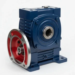
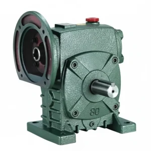
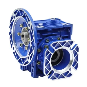
The WK Series worm gear reducer is the W family’s widest-range hollow bore unit — extending shaft-mount hollow bore worm reduction from size 50 all the way to size 200, with output bore diameters from Ø20 mm to Ø85 mm and a housing geometry drawn directly from the W series’ proven dimensional convention. The WK maintains the W series’ through-shaft solid input accessible from both housing sides, while the FCWK variant replaces that through-shaft with an IEC B5 motor-mounting flange — allowing either motor configuration to be specified against the same hollow bore output geometry. At size 200, the WK reaches output bore Ø85 mm with bore depths of 420 mm — the deepest, largest-diameter hollow bore available in the W family and substantially beyond the Ø70 mm maximum that the WA/WS series provides at equivalent frame sizes. For Australian manufacturers, OEM machine builders, and maintenance engineers across Sydney, Melbourne, Brisbane, Perth, and Adelaide who require W-series hollow bore capacity at frames above size 155 — or who need larger bore diameters at any frame — the WK and FCWK are the only W-family hollow bore units that deliver both. Manufactured to ISO 9001:2015, designed per AGMA 6034, and supplied by Ever-Power Worm Gear Reducer Co., Ltd. (Australia), 27 Harley Crescent, Condell Park NSW 2200.
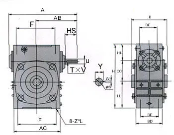
Key Specifications & Parameters — WK Series (WK and FCWK Variants)
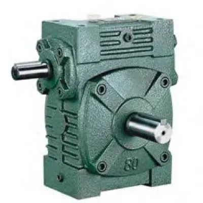
WK — Through-Shaft Input
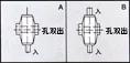
Solid input shaft extends from both housing faces — motor couples via jaw coupling to either side. Unused side fitted with blanking cap per AS 4024.1. W-class hollow bore output. Sizes 50–200.
FCWK — IEC Flange Input
IEC B5 motor flange replaces through-shaft input — motor bolts directly to flange face without coupling. W-class hollow bore output unchanged. No input coupling required. Sizes 50–200.
All parameters per ISO 9001:2015, AGMA 6034, and DIN 3975. Bore tolerance H7/DIN 286.
| Size | Ratio | Centre Dist. A (mm) | Hub Width B (mm) | Overall Length AC (mm) | Height H (mm) | Input Stub HL (mm) | Input Shaft Ø (mm) | Output Bore Ø (mm) | Weight (kg) |
|---|---|---|---|---|---|---|---|---|---|
| 50 | 10:1–60:1 | 175 | 107 | 115 | 150 | 35 | 30 | Ø20 | 6 |
| 60 | 10:1–60:1 | 195 | 117 | 126 | 177 | 42 | 40 | Ø25 | 8.5 |
| 70 | 10:1–60:1 | 234 | 131 | 155 | 215 | 55 | 40 | Ø30 | 12.5 |
| 80 | 10:1–60:1 | 264 | 144 | 174 | 250 | 65 | 50 | Ø35 | 20 |
| 100 | 10:1–60:1 | 322 | 175 | 224 | 310 | 80 | 50 | Ø40 | 33 |
| 120 | 10:1–60:1 | 385 | 200 | 264 | 370 | 95 | 65 | Ø45 | 50 |
| 135 | 10:1–60:1 | 435 | 212 | 304 | 425 | 105 | 75 | Ø60 | 77 |
| 155 | 10:1–60:1 | 494 | 312 | 330 | 461 | 103 | 85 | Ø70 | 100 |
| 175 | 10:1–60:1 | 548 | 334 | 370 | 521 | 123 | 85 | Ø80 | 140 |
| 200 | 10:1–60:1 | 688 | 346 | 420 | 575 | 130 | 95 | Ø85 | 200 |
What Is the WK Series and Why Does It Extend to Size 200?
The WK is the W family’s hollow bore unit that uses the full W series housing geometry — the same housing that the standard W series solid-shaft unit uses, with its characteristic taller housing profile, larger output shaft section (in the form of the hollow bore hub), and the wider bearing span that gives the W series higher overhung load capacity than the WP series at equivalent centre distances. This distinguishes the WK from the WA/WS series, which while also being W family hollow bore units, use a housing geometry more closely aligned with the WP/WPKA convention.
The most significant practical distinction is size 200: the WK extends to size 200 with a Ø85 mm output bore and a 200 kg housing — well beyond the WA/WS maximum of size 200 at Ø70 mm. At size 175–200, the WK provides bore diameters (Ø80–Ø85 mm) that are simply not available in any other W-family hollow bore configuration and are required for the large-diameter shaft-mount applications found in Australian mineral processing rotary drum drives, large material handling trommels, and heavy conveyor head shafts in mining and agricultural bulk handling.
The FCWK variant adds the IEC B5 motor-mounting flange on the input side — the same flange-and-housing approach used in the FCWD — eliminating the input coupling from the WK drive train. This allows IEC-frame motors to bolt directly to the FCWK without alignment, motor bases, or coupling guards, while the W-class hollow bore output is unchanged.
WK vs WA/WS — When to Specify Which W Family Hollow Bore Unit
| Feature | WA Series | WS Series | WK Series |
|---|---|---|---|
| Max bore Ø | Ø70 mm (size 200) | Ø70 mm (size 200) | Ø85 mm (size 200) |
| Bore Ø at size 135 | Ø55 mm | Ø55 mm | Ø60 mm |
| Housing geometry | WA/WS convention | WA/WS convention | W series (taller, heavier) |
| IEC flange variant | FCWDA | FCWDS | FCWK |
| Best for | Standard smooth loads, WA-convention machines | Shock loads, WS-convention machines | Large bore (Ø60–Ø85 mm), W-class housing, large frames |
How to Select WK or FCWK — Selection Guide for Australian Engineers
- Choose WK When: (a) driven shaft diameter exceeds the WA/WS maximum bore Ø at your frame size; (b) the machine requires W-series full-depth housing geometry; (c) frame size 175 or 200 is required and hollow bore output is needed; or (d) you are replacing an existing WK unit in legacy machinery.
- WK (Coupling Input) or FCWK (IEC Flange)? Specify FCWK when an IEC-frame motor is available and direct motor mount is preferred — eliminating the input coupling, motor base, and alignment procedure. Specify WK when through-shaft input from either side is a functional requirement (secondary encoder, hand-wheel, or second motor on the opposite stub).
- Calculate Torque and Frame Size: WK/FCWK rated torques follow the W series convention at each frame size. Apply service factor (SF 1.25–2.0) and select the smallest WK frame whose rated output torque ≥ design torque.
- Confirm Bore Diameter: Standard WK bore diameters are listed in the spec table. For driven shafts outside these standard dimensions, custom boring is available on a 2–3 week lead time — specify at order time.
- Guard Unused Input Stub (WK): The unused through-shaft stub must be guarded per AS 4024.1 before commissioning. Stub shaft cover plates for W series (not WP series) bolt patterns are stocked for all WK frame sizes.
Accessories We Also Supply: Through-shaft stub cover plates (AS 4024), W-family torque arm kits (WK/FCWK specific), shrink disc assemblies (Ø35+ bores), DIN 6885 parallel keys (all standard sizes), replacement oil seals, and jaw couplings for WK through-shaft input diameters. Contact Ever-Power Australia.
WK and FCWK Applications in Australian Industry
- Large Rotary Drum Shaft Drives (WA Mining, QLD Processing): WK 175–200 on rotary drum and trommel trunnion shafts where bore diameter requirements (Ø80–Ø85 mm) exceed what any WA/WS unit provides and the W-series housing geometry and higher bearing span are required for sustained radial loads. FCWK variant where IEC motor direct mount simplifies maintenance in the confined overhead positions common in mineral processing drum installations.
- Heavy Conveyor Head Shaft Drives (QLD, NSW, WA): WK 135–155 on bulk handling conveyor head shafts with large-diameter driven shafts (Ø60–Ø70 mm) in Australian grain receival, minerals processing, and quarry operations where the WA/WS bore would be too small and the WPKS bore diameter (WP convention) does not match the existing shaft.
- Agricultural Auger and Feeder Shaft Drives (Regional QLD, NSW, SA, WA): WK 80–120 on grain and fertiliser auger shaft drives where the W-series housing geometry is specified and bore diameters at Ø35–Ø45 mm with the W-class housing depth provides better shaft engagement than equivalent WA/WS units at the same frame size.
- Legacy WK Machine Replacement (All Australian States): The WK and FCWK provide direct dimensional replacement for existing WK units in Australian food, packaging, material handling, and agricultural machinery — maintaining W-series housing dimensions, bore diameters, and torque arm attachment points while optionally upgrading the input from through-shaft coupling (WK) to IEC motor flange (FCWK).
What Australian Customers Say About the WK Series
“WK 175 on our WA mineral processing drum drive — needed Ø80 mm bore and 140 kg W-class housing. No other W family hollow bore unit goes to Ø80 at this frame size. Ever-Power had it in stock and delivered in 11 days to the Pilbara. Exactly the unit we needed.”
— Darren M., Maintenance Engineer, Pilbara WA
“FCWK 120 on our Brisbane grain conveyor head shaft drive. IEC 112B5 brake motor flanges directly, Ø45 mm shaft goes into the bore. The W-class housing height fits our machine envelope perfectly — WP family units are shorter and wouldn’t have cleared the machine frame. 18 months without issue.”
— Nathan C., Conveyor Engineer, Brisbane QLD
“WK 135 replacing an old unit in our Sydney food plant. Exact dimensional match — same bore diameter, same torque arm holes, same mounting footprint. We needed Ø60 bore which WA/WS couldn’t provide at size 135 (their max is Ø55). Good product; 4 stars because size 135 needed 12 days when sizes 100/120 were in stock same day.”
— Alice N., Plant Manager, Sydney NSW
“FCWK 155 on our agricultural trommel shaft in SA. Size 155 with Ø70 bore and IEC 132B5 motor direct mount. The W-series housing is taller than WP equivalents so it fits the machine base perfectly. No coupling, no motor base, no alignment — just bolt the motor on and slide the shaft in.”
— Marcus L., Agricultural Engineer, Riverland SA
Why Choose Ever-Power for WK Series Worm Reducers in Australia?
Ever-Power Worm Gear Reducer Co., Ltd. (Australia) at 27 Harley Crescent, Condell Park NSW 2200 is one of the few Australian suppliers maintaining stock of WK units across all ten frame sizes including 175 and 200 — sizes that most competitors carry on order only. Our engineering team provides free WK vs WA/WS bore diameter and housing geometry comparisons, and WK vs FCWK input configuration recommendations. Visit About Us and technical reference at worm-gearbox.top.