Description
The NMRV-F aluminium alloy worm gearbox with flange output addresses one of the most common installation challenges for Australian manufacturers: connecting a right-angle worm gear reducer directly to a machine’s bolt-circle flange without shaft couplings, adaptor plates, or precision-drilled mounting feet. With a standard FA short-flange or FB long-flange output that mates directly to IEC and PAM standard bore flanges on fans, pumps, centrifuges, and conveyor drives, the NMRV-F reduces installation time by up to 60% compared with conventional shaft-and-coupling arrangements, while eliminating the periodic coupling alignment maintenance that accounts for an estimated 30–40% of planned gearbox-related downtime in Australian packaging and food processing plants. Available in eleven frame sizes from NMRV 025 to NMRV 185, with gear ratios from 5:1 to 100:1 and motor power from 0.06 kW to 15 kW, the NMRV-F is manufactured to ISO 9001:2015 and supplied across Sydney, Melbourne, Brisbane, Adelaide, and Perth by Ever-Power Worm Gear Reducer Co., Ltd. (Australia), 27 Harley Crescent, Condell Park NSW 2200.
Key Specifications & Parameters — NMRV-F Worm Gearbox
Full technical parameters for the NMRV-F series across all eleven standard frame sizes. Design references include ISO 9001:2015, AGMA 6034, and DIN 3975.
| Parameter | Specification |
|---|---|
| Series / Frame Sizes | NMRV-F / NRV-F: 025, 030, 040, 050, 063, 075, 090, 110, 130, 150, 185 |
| Gear Ratio Range | 5:1, 7.5:1, 10:1, 15:1, 20:1, 25:1, 30:1, 40:1, 50:1, 60:1, 80:1, 100:1 |
| Motor Power Range | 0.06 kW – 15 kW |
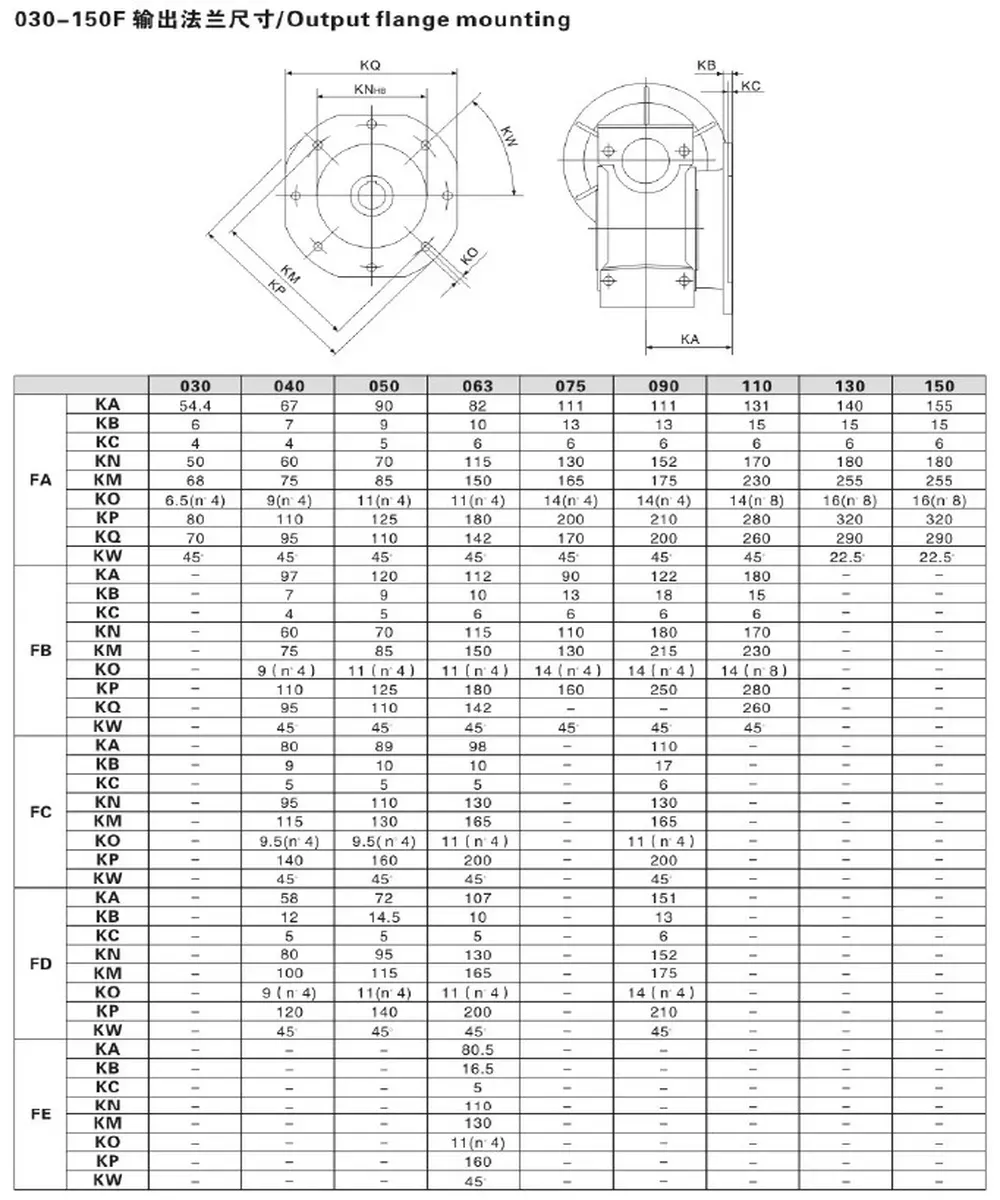
| Output Type | FA (short flange) or FB (long flange); solid shaft, hollow shaft, torque arm also available |
| Housing Material (size 025–090) | Die-cast aluminium alloy (ADC12) — shot-blasted, phosphated, epoxy painted |
| Housing Material (size 110–150) | Cast iron (GG25) — zinc-phosphate primed, epoxy topcoat |
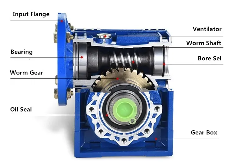
| Worm Wheel | Special wearable nickel-bronze alloy (CuSn10Ni1) |
| Worm Shaft | 20Cr steel — carburised & nitrided, HRC 58–62 |
| Oil Seal | NAK or SKF — Viton or NBR options |
| Bearing | SKF or C&U deep-groove ball bearings |
| Lubricant | Synthetic or mineral ISO VG 220 worm gear oil (Shell Omala) |
| Flange Standard | PAM / IEC (B5 / B14) |
| Mounting Directions | All six orientations — omnidirectional mounting |
| Colour | Blue / Silver Grey / Customised |
| Quality Standard | ISO 9001:2015; gear quality to DIN 3975 / AGMA 6034 |
What Is an NMRV-F Aluminium Worm Gearbox with Flange Output?
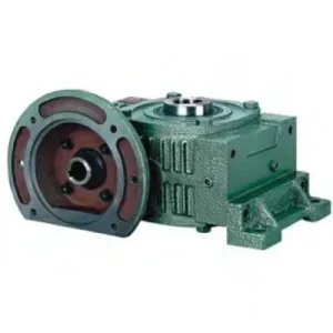
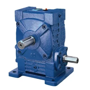
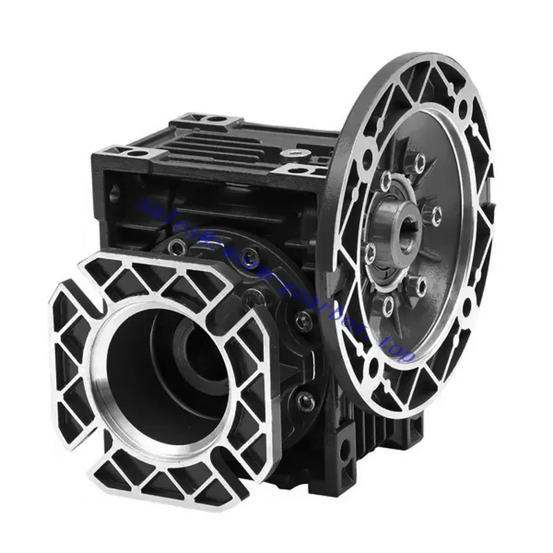
The NMRV-F is the flange-output variant of the internationally standardised NMRV right-angle worm reducer family. Where the standard NMRV delivers power via a solid keyed shaft that typically requires a separate shaft coupling to connect to the driven machine, the NMRV-F output face incorporates a precision-machined centring spigot and bolt-circle flange dimensioned to PAM and IEC standards. This allows direct bolted connection to the driven machine’s mating flange — no coupling, no key-and-setscrew engagement, no alignment shims.
The FA (short flange) variant positions the output flange close to the housing face — the preferred arrangement for compact machine designs and horizontal output shaft orientations. The FB (long flange) variant extends the output shaft further from the housing, allowing connection to machines with deeper flange recesses or where the gearbox must clear a machine frame member before reaching the driven component. Both FA and FB are available across the full NMRV-F size range from 025 to 185.
The aluminium alloy die-cast housing (ADC12) used for NMRV-F sizes 025–090 provides excellent corrosion resistance for Australian coastal industrial and food processing environments, while the high thermal conductivity of the alloy — approximately 4× higher than cast iron — ensures that heat generated at the worm mesh is rapidly conducted to the housing surface and dissipated without requiring supplementary cooling fans in most standard-duty applications. The larger NMRV-F sizes (110–185) use grey cast iron (GG25) housings for their higher structural rigidity under the elevated torques these frames produce.
Types and Output Configurations of the NMRV-F Series
The NMRV-F product family offers significant configuration flexibility. The following table details the available output and input permutations most commonly requested by Australian machinery builders:
| Configuration Code | Output | Input | Best For |
|---|---|---|---|
| NMRV-FA | Short flange (FA) with centring spigot | Solid input shaft or motor flange | Fans, pumps, compact drives |
| NMRV-FB | Long flange (FB) extended shaft | Solid input shaft or motor flange | Deep-recess flange machines |
| NRV-FA (without motor flange) | FA flange output | Worm shaft extension only | Chain/belt or gearbox cascade input |
| NMRV-F + VS (combined) | Hollow shaft + flange | IEC motor flange | Shaft-mounted with flange reaction |
Precision Production: Materials, Quality Control, and Compliance
The NMRV-F is produced under a documented quality management system certified to ISO 9001:2015. The following material and process specifications define the product quality that Australian manufacturers have come to expect from this series:
- Nickel-Bronze Worm Wheel (CuSn10Ni1): The nickel addition in the worm wheel alloy increases the hardness by approximately 8–12 HB compared with standard CuSn10 tin-bronze, improving surface fatigue resistance under high-cycle loading. This alloy grade is specified in the ASTM B427 nickel-bronze standard and is particularly effective in high-ratio (50:1 and above) applications where worm wheel sliding velocity is elevated.
- 20Cr Worm Shaft with Carburising and Nitriding: Unlike many competing products that use only carburising, the NMRV-F worm shaft undergoes both carburising (surface carbon enrichment to 0.8–1.0% C at 0.8–1.2 mm depth) and gas nitriding (surface nitrogen enrichment to approximately 0.1–0.15 mm additional depth). The dual treatment produces a surface hardness of HV 900–1000 at the thread flanks, significantly exceeding the minimum recommended in DIN 3990 for worm gear durability calculations. This hardness level ensures the worm retains its ground profile under the compressive contact stresses generated at the worm-bronze interface during extended service.
- SKF & NAK Brand Components: All oil seals are sourced from SKF or NAK — two of the bearing and seal brands most commonly specified by Australian industrial OEMs and service organisations, simplifying spare-parts procurement through existing approved supplier channels. Bearings are from SKF or C&U, both of which are registered with Australian Standards testing frameworks.
- Shell Lubricant: All NMRV-F units are pre-filled with Shell Omala S2 G 220 (ISO VG 220 mineral worm gear oil) as standard, the most widely available and commonly specified worm gear oil across Australian industrial facilities. Shell Omala is a recognised brand in Australian manufacturing and is readily available for top-up and oil changes through industrial lubricant distributors in Sydney, Melbourne, Brisbane, and Perth.
How to Select the Right NMRV-F Worm Gearbox — Step-by-Step Guide
Correct selection of the NMRV-F involves both standard gearbox sizing parameters and the specific flange output geometry requirements of your driven machine. This guide covers both aspects:
- Step 1 — Determine Output Speed & Torque: Calculate required output speed from your process requirement. Calculate required output torque = (process load force × radius) or (process power × 9550 / output rpm). Apply a service factor of 1.25 (smooth load) to 2.0 (heavy shock) to obtain design torque.
- Step 2 — Select Ratio: Divide your 4-pole motor speed (1,450–1,500 rpm for 50 Hz Australian mains) by required output speed to get the nominal ratio. Select the closest standard ratio from the NMRV-F table (5, 7.5, 10, 15, 20, 25, 30, 40, 50, 60, 80, or 100). For ratios above 100:1, consider the PC+NMRV combination unit.
- Step 3 — Select Frame Size: From the NMRV-F datasheet, identify the frame size whose rated output torque at your chosen ratio equals or exceeds your design torque. For continuous duty in Queensland or Western Australia (ambient temperatures 35–45 °C common in summer), also verify that the thermal rated input power equals or exceeds your motor’s shaft power output.
- Step 4 — Specify Flange Output Type (FA or FB): Measure the driven machine’s flange face-to-shaft-end distance. If the gearbox can position its output face directly against the machine flange, specify FA. If the machine flange is recessed behind a frame member requiring additional axial reach, specify FB and confirm the FB shaft length extension is sufficient.
- Step 5 — Confirm Flange Bolt Circle Dimensions: The NMRV-F output flange follows PAM/IEC bolt-circle standards. Provide the PCD (pitch circle diameter), number of bolts, bolt diameter, and centring spigot diameter of your driven machine flange for confirmation. Non-standard flanges can be machined to customer drawings.
- Step 6 — Select Housing Material & Sealing Option: For corrosive environments (coastal locations, chemical duty, food washdown), specify aluminium housing (NMRV-F 025–090) with Viton oil seals. For high-torque applications above the aluminium frame range, use the cast-iron housing sizes (110–185) with NBR seals standard or Viton upgrade.
Accessories We Also Supply for NMRV-F: FA/FB flange adaptor plates, output shaft extensions, IEC motor adaptors (B5/B14), torque arm kits, mounting feet, oil-fill plugs and breather vents, and replacement oil seals (NBR and Viton). Contact our team at Contact Us for a complete accessory quotation alongside your gearbox order.
NMRV-F Worm Gearbox Applications Across Australian Industry
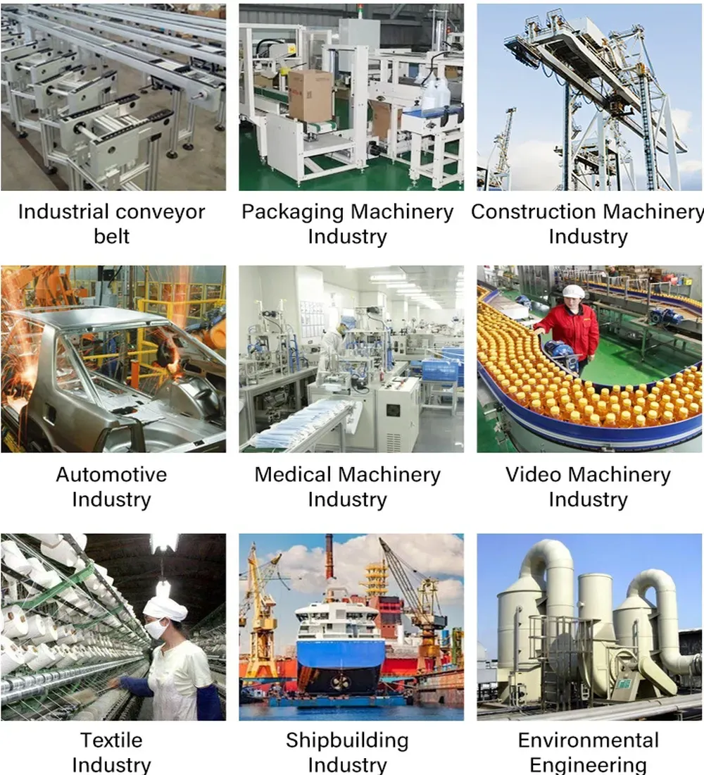
The direct flange-mount output of the NMRV-F makes it the preferred solution in industrial sectors where coupling-free, concentric drive connections are required. Active deployment sectors across Australia include:
- Food & Beverage Machinery (Sydney, Melbourne, Brisbane): Mixers, blenders, filling machines, and bottle conveyors in food processing plants require direct-drive flange connections that can withstand CIP (clean-in-place) chemical washdowns. The aluminium housing with Viton seals meets this requirement while complying with Australian food safety equipment standards.
- Ceramics & Glass Manufacturing: Kiln conveyor drives and glass-forming equipment in ceramics and glass plants benefit from the NMRV-F’s high torque density at low output speeds — ratios of 40:1 to 100:1 are commonly selected for kiln car drives where precise, vibration-free movement is critical to product quality.
- Chemical & Packing Industries (Adelaide, Perth): Chemical mixing vessels, powder-filling equipment, and industrial packaging lines in Perth and Adelaide increasingly specify aluminium-housing reducers for their corrosion resistance to chemical vapours and the weight reduction benefit for portable or elevated-mount installations.
- Dyeing & Textile Finishing (Melbourne, Geelong): Tension rollers, jet dyeing machines, and stenter drives in the Victorian textile sector use NMRV-F units for their combination of compact form factor, direct flange mounting to roller shafts, and sealed aluminium construction resistant to steam and detergent exposure.
- Woodworking Machinery: Feed drives, thickness planer tables, and edge-banding machines in woodworking operations across New South Wales and Queensland require gearboxes that can handle the cyclic impulse loads of timber feed without the coupling shock-absorption issues that can cause premature wear in competing designs.
How to Install an NMRV-F Flange Output Worm Gearbox — Step-by-Step
Correct installation is critical to achieving rated service life. The following procedure applies to a standard NMRV-F with FA flange output being mounted to a driven machine flange and driven from an IEC motor on the input flange:
- Inspect Before Installation: Verify the unit has not been damaged in transit. Check oil level at the sight plug for the intended mounting orientation. Confirm oil fill level is at the centre of the sight glass (for horizontal-worm-shaft mounting) or at the upper fill mark (for vertical mounting) before connecting to the drive system.
- Mount IEC Motor to Input Flange: Slide the motor shaft into the IEC input flange bore. Hand-tighten the three or four flange bolts (grade 8.8, hex-socket M8 or M10 depending on flange size) then torque to DIN 912 specification — typically 25 N·m for M8 and 50 N·m for M10. Do not apply thread-locking compound to motor flange bolts, as these must be removable for future motor replacement.
- Locate on Machine Flange: Insert the output FA/FB flange centring spigot into the driven machine’s mating bore. Verify the bolt-circle holes align. Apply a light film of anti-seize compound to the output flange face bolts before inserting. Hand-tighten all bolts before final torquing to ensure even seating of the spigot in the bore.
- Torque Output Flange Bolts: Torque output flange fasteners to the manufacturer’s specification in a cross-pattern sequence (180° apart, then 90° pairs). Final torque values range from 30 N·m (NMRV-F 025) to 180 N·m (NMRV-F 150) for grade 10.9 fasteners — refer to the dimensional datasheet for your frame size.
- Check Mounting Direction and Oil Level: After installation in the intended orientation, re-verify oil level at the orientation-specific fill port and adjust if necessary. If the mounting orientation was changed from factory-fill orientation, drain and refill oil to the correct level for the new orientation before initial run-in.
- Initial Run-In: Run the gearbox unloaded for 30 minutes, then under 50% load for 2 hours before applying full rated load. Monitor housing temperature during run-in — normal stabilised operating temperature is 40–70 °C above ambient. Temperatures above 90 °C indicate an oversized service factor, insufficient lubrication, or incorrect mounting orientation.
What Australian Engineers Say About the NMRV-F Worm Gearbox
“Fitted NMRV-F 063 units to 12 mixer drives in our Melbourne food plant. The FA flange mount to the vessel bottom flange eliminated the coupling assemblies that we’d had ongoing issues with. Zero leakage with the Viton seals — passed our weekly washdown inspections every time for 10 months.”
— Michelle H., Plant Manager, Melbourne VIC
“The nickel-bronze worm wheel in the NMRV-F is noticeably harder than the standard bronze spec we used previously. We run 80:1 ratio at near-continuous duty in our ceramics kiln drives in Adelaide — previous units were showing significant wheel wear at 8,000 hours. The NMRV-F units still look new at the same interval.”
— David S., Maintenance Engineer, Adelaide SA
“We source NMRV-F units in bulk for our woodworking machine OEM business in Brisbane. The SKF bearings and seals give our customers confidence in the specification — they match what’s already in our machine spindles. Ever-Power’s supply consistency and pricing has been excellent over 2 years of ordering.”
— Simon W., Purchasing Manager, Brisbane QLD
“Used NMRV-F 040 units on a chemical dosing system in Perth. Aluminium housing has held up perfectly in our mild acid vapour environment. The FB flange version was exactly what we needed to reach the recessed pump shaft. Would be 5 stars but we had to wait 3 weeks for a non-standard bore size.”
— Chris P., Process Engineer, Perth WA
Why Choose Ever-Power for NMRV-F Worm Gearboxes in Australia?
At Ever-Power Worm Gear Reducer Co., Ltd. (Australia), 27 Harley Crescent, Condell Park NSW 2200, we maintain comprehensive stock of NMRV-F units across all eleven frame sizes and the most common ratio/configuration combinations. Standard orders are fulfilled within 5–10 business days, with freight to Eastern seaboard locations typically reaching customers within 7–12 days total from order confirmation. Our engineering team provides free pre-purchase application review and post-installation technical support. Read more about our capabilities on our About Us page.
- ISO 9001:2015 certified — documented quality system covering incoming materials, process control, and outgoing inspection
- International brand components: SKF/NAK seals, SKF/C&U bearings, Shell lubricants — the same brands used by leading Australian industrial OEMs
- Customisation available: Non-standard bore diameters, extended shafts, special keyways, stainless steel shafts, IP65 sealing, and OEM labelling — lead time 2–3 weeks
- Volume pricing: Discounts available for orders above 10 units — contact us for a project pricing schedule
- Australian Standards compliance: Products referenced against relevant AS standards for machinery applications; documentation available for procurement compliance records
For extended technical specifications, cross-reference charts, and product comparison tools, visit our partner resource site at worm-gearbox.top.