Description
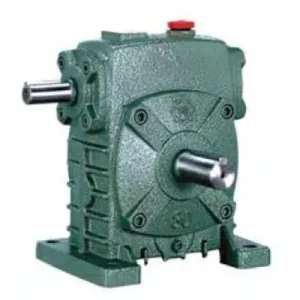
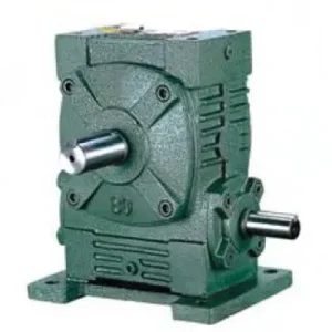
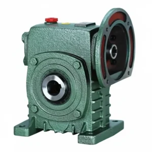
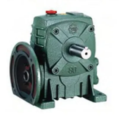
Every flexible shaft coupling in an industrial drive system introduces an alignment procedure, a maintenance interval, and a failure mode. The DA Series (WPDA) worm gear reducer eliminates all three at the motor-gearbox interface by replacing the conventional coupling arrangement with a machined IEC B5 motor-mounting flange built directly into the reducer housing face. An IEC-frame motor slides straight onto the WPDA input flange — concentric, self-locating, and secured with four bolts — without shims, dial gauges, flexible elements, or coupling guards. The result is a compact, factory-aligned motorised worm gear drive unit that reduces installation time by up to 70% compared with a separate motor-plus-coupling-plus-reducer arrangement, while eliminating the coupling misalignment that accounts for an estimated 30–35% of premature worm gearbox bearing failures in Australian industrial facilities. Covering sizes 50 through 155, input powers from 0.18 kW to 5.5 kW, and gear ratios from 10:1 to 60:1, the WPDA is the specification of choice for Australian manufacturers in Sydney, Melbourne, Brisbane, and Perth where compact motorised worm drive units are required. Supplied by Ever-Power Worm Gear Reducer Co., Ltd. (Australia), 27 Harley Crescent, Condell Park NSW 2200.
Key Specifications & Parameters — DA Series (WPDA) Worm Gear Reducer
All parameters comply with ISO 9001:2015, AGMA 6034 rated torque methodology, and IEC 60034 motor flange dimensional standards.
| Size | Input Power (kW) | Ratio Range | Centre Dist. A (mm) | Overall Length B (mm) | Height H (mm) | IEC Flange LA (mm) | Output LS (mm) | Weight (kg) |
|---|---|---|---|---|---|---|---|---|
| 50 | 0.18 | 10:1 – 60:1 | 165 | 175 | 180 | 115 | 40 | 7 |
| 60 | 0.37 | 10:1 – 60:1 | 185 | 190 | 205 | 130 | 50 | 11 |
| 70 | 0.55 | 10:1 – 60:1 | 215 | 215 | 240 | 145 | 60 | 16 |
| 80 | 0.75 | 10:1 – 60:1 | 250 | 240 | 280 | 160 | 65 | 24 |
| 100 | 1.5 | 10:1 – 60:1 | 310 | 255 | 363 | 165 | 75 | 38 |
| 120 | 3.0 | 10:1 – 60:1 | 370 | 305 | 435 | 200 | 85 | 65 |
| 135 | 4.0 | 10:1 – 60:1 | 415 | 345 | 490 | 225 | 95 | 85 |
| 155 | 5.5 | 10:1 – 60:1 | 442 | 402 | 536 | 265 | 110 | 120 |
What Is the DA Series (WPDA) and Why Does the IEC Flange Matter?
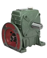

In the WP family model naming convention, the suffix A denotes the foot-mount base configuration (as in WPA), but when prefixed with D, the DA (WPDA) designates a configuration where the motor connects directly to the reducer via a machined IEC B5 flange — no separate coupling, no alignment procedure, and no intermediate motor base plate.
The IEC B5 input flange on the WPDA is machined concentrically with the worm shaft axis to within 0.03 mm TIR, ensuring that any standard IEC B5-frame motor mounted to it achieves automatic shaft concentricity at motor-frame tolerance — typically 0.05–0.10 mm TIR total system runout. This is far better than the 0.1–0.5 mm misalignment that typically exists in a manually aligned coupling-based arrangement after installation, and eliminates the primary cause of worm shaft input bearing failure: radial load from coupling misalignment imposed continuously on the bearing inner race.
The WPDA retains the standard WPA foot-mount base — the same four anchor bolts, the same foot pad dimensions — so the reducer can still be bolted to a machine base or concrete pad exactly as a WPA would be. The WPDA thus combines the positioning stability of a foot-mount unit with the alignment precision of a flanged drive, making it the favoured configuration for packaging machinery, conveyors, and automated assembly systems across Australian manufacturing plants in Sydney, Melbourne, Brisbane, and Adelaide where space constraints prevent separate motor base arrangements.
DA Series Configuration Variants and IEC Flange Options
| Variant | IEC Flange Type | Motor Frame Range | Output Configuration | Typical Application |
|---|---|---|---|---|
| WPDA (standard) | IEC B5 (face-mount) | 56–132 (size-dependent) | Solid output shaft, single side | Compact motorised drives, packaging machinery |
| WPDA-B14 | IEC B14 (face-mount, smaller) | 56–90 (size-dependent) | Solid output shaft, single side | Small-frame servo/stepper motor applications |
| WPDAS (WPDA+WPS housing) | IEC B5 | 63–160 | Extended output shaft, higher overhung load | Chain-drive conveyors with direct motor mount |
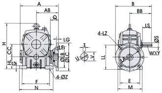
Manufacturing Precision: How the WPDA IEC Flange Is Machined
The dimensional accuracy of the IEC B5 input flange face is critical to the WPDA’s performance advantage over coupling-based arrangements. The following machining sequence ensures the flange geometry meets IEC 60034-7 motor mounting face tolerances:
- Housing Casting: GG25 grey-iron housings are produced in permanent metal moulds. All critical surfaces are left with machining allowance of 2–3 mm — no cast surface is used as a precision reference.
- Single-Setup CNC Machining: The worm shaft bore, input flange face, and flange pilot bore are all machined in a single CNC fixture setup, ensuring they share a common axis reference. This is the step that guarantees the 0.03 mm TIR concentricity between motor shaft and worm shaft when the motor is installed.
- Flange Face Flatness: The IEC B5 flange face is milled to a flatness of 0.02 mm/100 mm, preventing any angular tilt of the motor shaft relative to the worm shaft axis that could generate a bending moment at the motor shaft bearing.
- Pilot Bore Tolerance: The flange pilot bore is machined to H7 tolerance per IEC 60034-7, providing a close-clearance location fit that self-centres the motor on the flange without requiring manual centering during installation.
- Worm Shaft Grinding and Assembly: After the housing is complete, the worm shaft (20CrMnTi, HRC 56–62) and bronze wheel (ZCuSn10Pb1) are assembled under controlled meshing-contact inspection per DIN 3975, with oil film and bearing pre-load set to specification before final fastener torquing.
How to Select the Right WPDA Frame Size — Step-by-Step Guide
- Motor Selection First: Because the WPDA’s IEC flange is sized to a specific motor frame range, the motor must be selected before the reducer frame size. Choose the motor IEC frame size based on your required input power and speed. The motor’s IEC B5 flange PCD and pilot diameter then determine the minimum WPDA frame size that can accommodate it.
- Confirm Ratio and Torque: Calculate required output torque with service factor (SF 1.25–2.0). Identify the WPDA frame size whose rated output torque at your ratio meets or exceeds the design torque.
- Check IEC Flange Compatibility: Confirm the motor’s IEC frame designation (e.g., 71B5, 80B5, 90LB5) matches the IEC flange option available for your chosen WPDA frame. Common pairings: WPDA-50 accepts 56B5–71B5; WPDA-80 accepts 71B5–100B5; WPDA-135 accepts 112B5–132B5. Non-standard pairings available as custom order.
- Verify Thermal Rating: For continuous-duty applications in Australian summer conditions (35–45 °C ambient in QLD and WA), confirm the WPDA thermal rated power ≥ motor kW after derating for ambient temperature. Specify synthetic ISO VG 220 oil if thermal margin is marginal.
- Specify Self-Locking Need: Ratios 20:1 and above are self-locking. For ratios 10:1 and 15:1 on gravity-loaded drives, specify a supplementary backstop or brake per AS 4024.
Accessories We Also Supply: IEC motor adaptor rings (for non-standard motor frame sizes), output shaft couplings and hubs, replacement oil seals (NBR and Viton), motor flange bolts (stainless steel for food/washdown environments), and foot-mount shim packs. Contact Ever-Power Australia for bundled pricing.
Applications of the WPDA in Australian Industry
The WPDA’s motor-direct flange mounting is particularly valued in Australian applications where machine envelope is constrained, installation labour cost is a significant budget line item, or where repeated motor changes are anticipated:
- Packaging Machinery (Sydney, Melbourne): Carton erectors, label applicators, and wrapping machines in Australian FMCG and pharmaceutical packaging plants routinely change motor specifications when production speeds change. The WPDA allows a different IEC-frame motor to be swapped onto the same reducer flange in under 20 minutes — no alignment tools required.
- Conveyor Systems (Brisbane, Perth): Belt conveyor head drives, roller-bed conveyors, and accumulation conveyor drives in warehouse and distribution centre applications across Queensland and Western Australia benefit from the WPDA’s compact motorised unit form factor, which allows closer conveyor-to-conveyor spacing than a separate motor-plus-coupling arrangement.
- Automated Assembly Equipment (Adelaide, Melbourne): Rotary indexing tables, pallet-handling stations, and transfer mechanisms in Australian automotive and electronics assembly plants require the combination of precise positioning and compact drive form that the WPDA + servo motor provides.
- Food Processing (Sydney, Brisbane): Mixing bowls, scraper blades, and filling augers in food production facilities where the motor must be fully enclosed within a splash-proof housing. The WPDA with IP65 sealed IEC motor presents no external coupling to harbour product residue — simplifying compliance with Australian food safety equipment standards AS/NZS 4696.
- Water Treatment and Infrastructure (Perth, Adelaide): Filter-press drives, sludge scrapers, and valve actuators in water treatment facilities across South Australia and Western Australia, where the combination of self-locking at 40:1–60:1 and direct motor mount enables simple, low-maintenance slow-speed actuator designs.
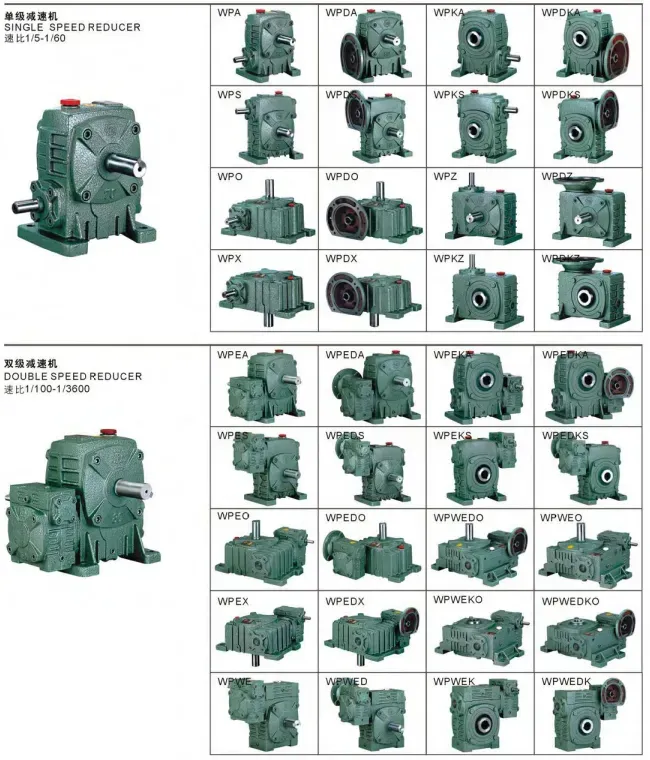
WPDA vs WPA — Which Should You Specify?
| Feature | WPA (Coupling Input) | WPDA (IEC Flange Input) |
|---|---|---|
| Motor connection | Flexible coupling + motor base | Direct IEC B5/B14 flange — no coupling |
| Alignment requirement | Dial gauge alignment — 30–60 min | None — self-aligning via pilot bore |
| Motor swap time | 1–3 hours (alignment + coupling) | 15–20 minutes (4 bolts) |
| Installed footprint | Larger — motor base + coupling guard | Compact — motor bolts directly to reducer |
| Input shaft bearing life | Affected by residual misalignment | Maximised — no coupling radial load |
| Motor compatibility | Any motor shaft diameter (via coupling) | IEC B5/B14 frame motors only |
| Unit cost | Lower (reducer only) | 5–12% higher — but coupling cost eliminated |
| Best for | Non-IEC motors; existing motor arrangements | New IEC motor installations; frequent motor changes |
What Australian Customers Say About the DA Series (WPDA)
“We retooled 16 conveyor drives in our Sydney distribution centre with WPDA 100 units. Motor swap-out now takes one of our fitters 18 minutes flat compared with nearly 2 hours before with the old coupling arrangement. The compact size also let us reduce our minimum conveyor gap by 120 mm — real space saving in a busy warehouse.”
— Marcus T., Facilities Engineer, Sydney NSW
“WPDA 80 at 40:1 on our Brisbane carton sealing machines. The direct flange mount with a 0.75 kW 80B5 motor is perfectly concentric — we had a constant vibration issue with the old coupling that caused premature bearing failure every 8–10 months. Been 14 months on the WPDA with no vibration issues at all.”
— Karen S., Maintenance Engineer, Brisbane QLD
“Using WPDA 60 units on our Melbourne automated assembly indexing tables with 90B14 servo motors. Positioning accuracy is excellent at 60:1. Only reason it’s not 5 stars is that we needed a slightly non-standard flange dimension for one motor variant — took 2.5 weeks for the custom option. Good result though.”
— Ryan L., Automation Engineer, Melbourne VIC
“We specify WPDA units as standard for all our food machinery builds in Adelaide. The IP65 motor-plus-WPDA combination passes our washdown testing, and the self-cleaning geometry — no external coupling to trap product — satisfies our food safety audit requirements. Ever-Power provides the compliance documentation we need.”
— Stephanie N., Design Engineer, Adelaide SA
Why Choose Ever-Power for WPDA Worm Gear Reducers in Australia?
Ever-Power Worm Gear Reducer Co., Ltd. (Australia) at 27 Harley Crescent, Condell Park NSW 2200 stocks WPDA units across all eight frame sizes in the most common ratio and IEC flange configurations. We provide free IEC flange-motor compatibility checks and confirmed dimensional quotes within one business day. For more about our team and capabilities visit our About Us page. Technical reference at worm-gearbox.top.
- ISO 9001:2015 certified — full quality documentation available for asset management records
- IEC 60034-7 compliant flange machining — guaranteed motor interchange at standard IEC frame dimensions
- 5–10 business day dispatch to all Australian states from Condell Park NSW 2200
- Custom IEC flange options for non-standard motor frames — 2–3 week lead time
- Food-grade lubricant pre-fill and Viton seal upgrade available for food and pharmaceutical applications