Description
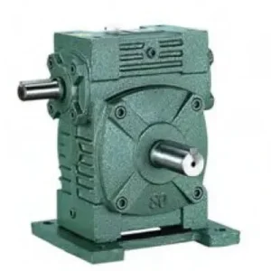
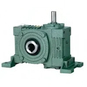
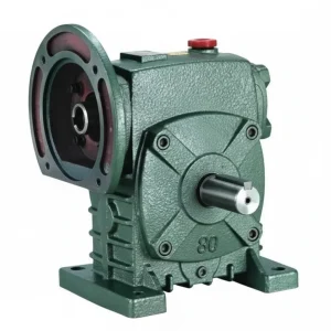
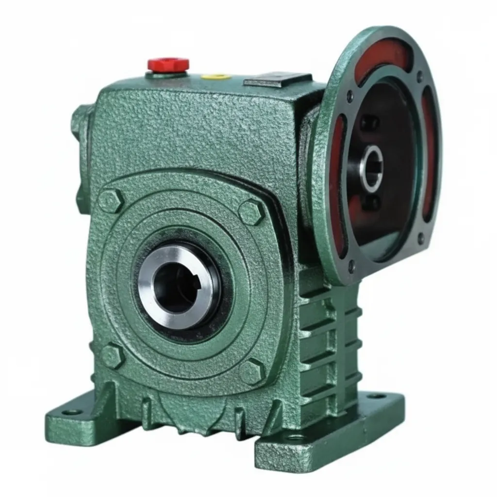
The WD Series (FCWD) worm gear reducer adds the one interface the standard W series lacks: a machined IEC B5 motor-mounting flange directly on the input housing face. Where the W series solid-shaft input requires a separate jaw coupling, motor base, and alignment procedure to connect an IEC-frame motor, the FCWD eliminates all three by presenting a flange face concentric with the worm shaft axis — the motor bolts straight onto it without any intermediate hardware. The W series’ substantial solid output shaft section, deeper bearing span, higher overhung load capacity, and larger housing height are retained fully, making the FCWD the correct specification for Australian engineers who need motor-direct IEC flange input alongside the W-class solid output shaft capacity that the lighter WPDA (WP family) cannot deliver. Covering sizes 50 through 155, input powers from 0.18 kW to 5.5 kW, and standard ratios from 10:1 to 60:1, the FCWD serves Australian manufacturers in Sydney, Melbourne, Brisbane, Adelaide, and Perth across food processing, packaging, conveyor, and material handling machinery. Manufactured to ISO 9001:2015, designed per AGMA 6034, and supplied by Ever-Power Worm Gear Reducer Co., Ltd. (Australia), 27 Harley Crescent, Condell Park NSW 2200.
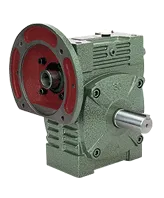
Key Specifications & Parameters — WD Series (FCWD) Worm Gear Reducer
All parameters per ISO 9001:2015, AGMA 6034, and IEC 60034-7 motor flange dimensional standards.
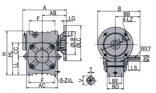
| Size | Input Power (kW) | Ratio Range | Centre Dist. A (mm) | Length B (mm) | Height H (mm) | Worm Stub HL (mm) | IEC Flange LA (mm) | Output Shaft Ø (mm) | Weight (kg) |
|---|---|---|---|---|---|---|---|---|---|
| 50 | 0.18 | 10:1–60:1 | 165 | 175 | 150 | 115 | 115 | Ø40 | 7 |
| 60 | 0.37 | 10:1–60:1 | 185 | 190 | 177 | 135 | 130 | Ø50 | 11 |
| 70 | 0.37–0.75 | 10:1–60:1 | 209 | 210 | 215 | 160 | 130 | Ø60 | 14 |
| 80 | 0.75–1.5 | 10:1–60:1 | 242 | 240 | 250 | 185 | 165 | Ø65 | 22 |
| 100 | 1.5 | 10:1–60:1 | 310 | 263 | 310 | 230 | 165 | Ø75 | 36 |
| 120 | 2.2–3.0 | 10:1–60:1 | 361 | 310 | 370 | 275 | 215 | Ø85 | 63 |
| 135 | 3.0–4.0 | 10:1–60:1 | 412 | 335 | 425 | 320 | 215 | Ø95 | 80 |
| 155 | 5.5 | 10:1–60:1 | 442 | 402 | 461 | 358 | 265 | Ø110 | 114 |
What Is the WD Series (FCWD) — IEC Flange Meets W-Class Output

The FCWD is understood most clearly by comparison with its closest relatives in each family. In the WP family, the WPDA provides IEC flange input and WPA-class output shaft — a compact unit ideal for light-to-medium duty with direct motor mount. In the W family, the standard W series provides the heavier W-class output shaft with deeper bearing span and higher overhung load capacity, but requires a coupling-and-base motor input. The FCWD occupies the intersection: IEC flange input (no coupling, no motor base, no alignment) combined with the W-class output shaft section — providing the larger Ø40–Ø110 mm output shaft diameter, deeper bearing span, and higher overhung load capacity of the W series, while eliminating the input coupling.
This combination matters specifically when the output shaft load — particularly overhung radial force from chain sprockets, belt pulleys, or gear pinions — exceeds what the WPDA can provide at the same input power, but direct IEC motor mounting is still required for installation efficiency or space reasons. At FCWD size 100, the output shaft is Ø75 mm versus Ø75 mm for the WPDA 100 — similar diameter, but with the W-class deeper bearing span that provides approximately 30–40% higher rated overhung load at equivalent shaft diameter, the same advantage the standard W series has over the WP family.
The IEC B5 input flange is machined concentrically with the worm shaft axis to within 0.03 mm TIR, providing factory-precision motor shaft alignment without the use of dial gauges or shims. The motor bolts to the flange face with four IEC-standard fasteners, and the entire motor-flange-reducer assembly is ready to operate immediately upon installation — with motor swap times of under 20 minutes for a trained fitter.
FCWD vs WPDA vs W Series — Choosing the Right Unit
| Feature | WPDA (WP family) | FCWD (W family) | W Series (standard) |
|---|---|---|---|
| Motor input | IEC B5 flange (direct) | IEC B5 flange (direct) | Through-shaft coupling |
| Output shaft class | WPA-class (standard) | W-class (heavier span) | W-class (heavier span) |
| Overhung load (size 100) | ~2,400 N | ~3,300 N (+38%) | ~3,500 N |
| Output shaft Ø (size 100) | Ø75 mm (WPDA conv.) | Ø75 mm (W conv.) | Ø75 mm (W conv.) |
| Alignment required | None (flange self-aligns) | None (flange self-aligns) | Yes (coupling alignment) |
| Best for | IEC motor, moderate OHL | IEC motor, high OHL, W-conv. machines | Through-shaft flexibility, size to 200 |
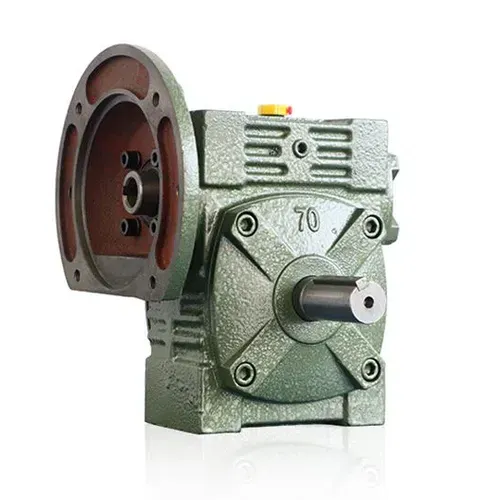
How to Select the FCWD — Step-by-Step Guide for Australian Engineers
- FCWD or WPDA? Calculate overhung load: F_OH = (2 × output torque) / sprocket PCD. Compare with WPDA rated OHL at your frame size. If F_OH exceeds 85% of the WPDA’s rated OHL, specify FCWD for its higher W-class bearing span. If F_OH is within the WPDA’s rating, WPDA is sufficient and lower cost.
- FCWD or W Series? If IEC motor direct mount is required or preferred — specify FCWD. If through-shaft input from either side is a functional requirement (secondary motor, encoder, hand-wheel on opposite side) — specify the W series solid-shaft unit with coupling input. If hollow bore output is needed — specify the WA or WS (W family hollow bore).
- Confirm IEC Motor Frame Compatibility: FCWD IEC flange acceptance ranges follow the same motor-to-reducer size pairings as the WPDA at equivalent centre distances. Confirm motor frame before ordering. Common pairings: FCWD-60 → 63B5, 71B5; FCWD-80 → 71B5, 80B5; FCWD-100 → 90B5, 100B5; FCWD-155 → 132B5, 160B5.
- Calculate Torque with Service Factor: FCWD rated output torques follow the W series convention at each frame size. Apply SF 1.25–2.0. Verify the rated torque at your ratio meets or exceeds design torque.
- Thermal Check for Australian Summer: Derate thermal power limit 10% per 10 °C above 20 °C reference ambient. For Queensland, WA, and NT summer conditions (35–45 °C ambient), specify synthetic ISO VG 220 oil if thermal margin is below 15%.
Accessories We Also Supply: IEC motor adaptor rings for non-standard motor frames, output shaft jaw and disc couplings, output sprockets (pilot bore and finished bore), motor support brackets (frame 100+), replacement oil seals (NBR and Viton), and foot-mount shim packs. Contact Ever-Power Australia for pricing.
WD Series (FCWD) Applications in Australian Industry
- Chain Conveyor Head Shaft Drives (Sydney, Melbourne, Brisbane): Chain conveyor drives where the head shaft sprocket creates an overhung radial force that exceeds the WPDA’s output bearing rating. The FCWD’s W-class bearing span handles this load while the IEC flange eliminates the input coupling and motor base, reducing total installation time and machine envelope compared with a separate W series unit plus motor arrangement.
- Legacy W-Convention Machines Requiring IEC Motor Upgrade (All States): When upgrading older W series machines to IEC-frame motors — eliminating obsolete motor frames and their associated couplings and motor bases — the FCWD allows the existing W-series dimensional mounting to be retained while adopting the IEC motor interface standard. No machine base modifications are required when replacing a W series unit with an FCWD of the same centre distance.
- Packaging and Food Processing (Sydney, Adelaide): Conveyor head drives, filling auger drives, and rotary table drives in Australian food and beverage plants where the combination of IEC brake motor direct mount (for hygienic enclosed drives) and W-class output shaft capacity for sprocket drives is required simultaneously.
- Agricultural and Irrigation Drives (QLD, SA, WA): Auger drives, pump drives, and irrigation pivot actuators in the 0.75–3.0 kW range where a modern IEC-frame motor must connect to a drive that was originally dimensioned around the W series convention. The FCWD bridging role between the two families makes it a frequent MRO choice for regional agricultural equipment servicing.
What Australian Customers Say About the WD Series (FCWD)
“Our Melbourne chain conveyor head drives needed IEC motor direct mount but the WPDA wasn’t enough for our sprocket OHL. The FCWD 100 at 30:1 with 90B5 motor was the answer — IEC flange input, W-class bearing span, the sprocket load is well within rating. 16 months in with no issues.”
— James C., Conveyor Engineer, Melbourne VIC
“We upgraded 12 W series units in our Sydney food plant to modern IEC 80B5 brake motors. The FCWD 80 allowed us to reuse the existing W-series dimensional mounting in the machine bases — no modifications. The IEC flange eliminates the old motor bases and coupling guards entirely. Installation was 20 minutes per unit.”
— Helen R., Plant Manager, Sydney NSW
“FCWD 70 on our Brisbane packaging filling auger drives. Direct IEC motor mount, W-class output shaft — perfect combination. 4 stars rather than 5 because we needed the 0.75 kW variant which is slightly less common than the 0.37 kW — took an extra 3 days. Great product otherwise.”
— Scott N., Production Engineer, Brisbane QLD
“FCWD 120 at 40:1 with 2.2 kW 112B5 motor on our grain auger head drive in SA. The W-class bearing span handles the auger chain load that made the WPDA 120 fail in 8 months. 22 months now without any bearing issues. The Ever-Power engineering team correctly diagnosed the OHL problem and recommended FCWD.”
— Bruce P., Grain Operations Manager, SA Riverland
Why Choose Ever-Power for FCWD Worm Reducers in Australia?
Ever-Power Worm Gear Reducer Co., Ltd. (Australia) at 27 Harley Crescent, Condell Park NSW 2200 stocks FCWD units across common frame sizes for 5–10 business day dispatch. Our engineering team provides free overhung load calculations, FCWD vs WPDA comparison analysis, and IEC flange compatibility confirmation — all in a single written recommendation within one business day. Visit About Us and technical reference at worm-gearbox.top.