Description
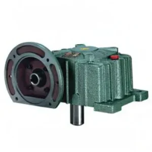
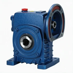
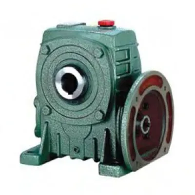
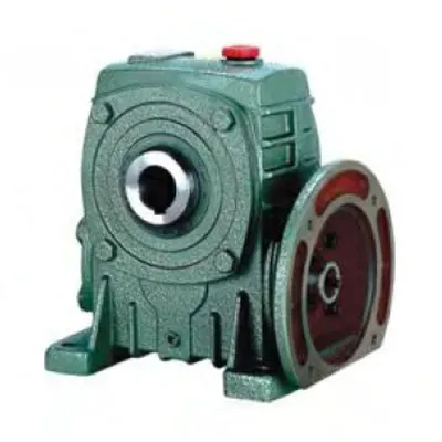
The most coupling-free worm gearbox in the WP family is the DKA Series (WPDKA). By integrating an IEC B5 motor-mounting flange at the input face and a hollow bore output through the worm wheel hub, the WPDKA removes every coupling from the drivetrain simultaneously — the motor bolts directly onto the input flange without a coupling at one end, and the driven shaft slides directly into the output bore without a coupling at the other end. For Australian OEM machine builders and plant engineers in Sydney, Melbourne, Brisbane, Adelaide, and Perth retrofitting drives into tight machine envelopes, this means two fewer rotating flexible elements, two fewer alignment procedures, and two fewer coupling-related failure modes — all in a single compact right-angle housing. Covering sizes 50 through 175, input powers from 0.18 kW to 7.5 kW, output bore diameters from Ø20 to Ø80 mm, and gear ratios from 10:1 to 60:1, the WPDKA represents the highest configuration density available in the WP worm reducer family. Manufactured to ISO 9001:2015, designed per AGMA 6034, and supplied by Ever-Power Worm Gear Reducer Co., Ltd. (Australia), 27 Harley Crescent, Condell Park NSW 2200.
Key Specifications & Parameters — DKA Series (WPDKA) Worm Gear Reducer
All parameters per ISO 9001:2015, AGMA 6034, and IEC 60034-7 motor flange standards. Bore tolerance H7 per DIN 286.
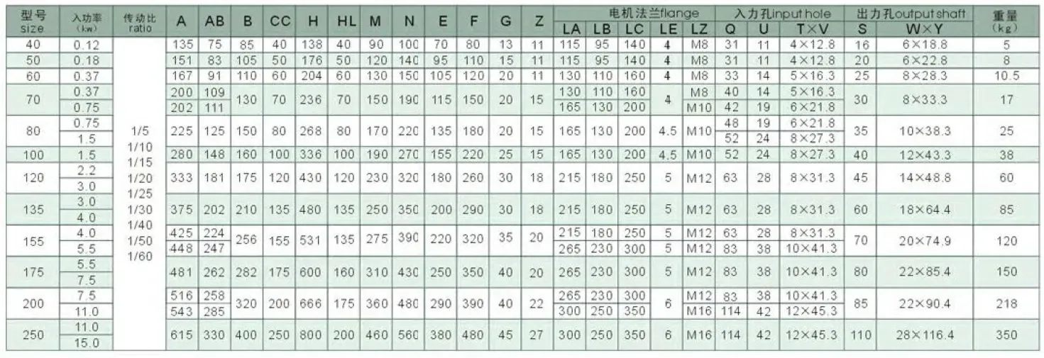
| Size | Input Power (kW) | Ratio Range | Centre Dist. A (mm) | Overall Length B (mm) | Height H (mm) | Bore Length HL (mm) | IEC Flange LA (mm) | Bore Ø (mm) | Weight (kg) |
|---|---|---|---|---|---|---|---|---|---|
| 50 | 0.18 | 10:1–60:1 | 155 | 107 | 180 | 50 | 115 | Ø20 | 8 |
| 60 | 0.37 | 10:1–60:1 | 170 | 117 | 210 | 60 | 130 | Ø25 | 10.5 |
| 70 | 0.55 | 10:1–60:1 | 200 | 131 | 243 | 70 | 145 | Ø30 | 15 |
| 80 | 0.75 | 10:1–60:1 | 228 | 144 | 273 | 80 | 160 | Ø35 | 22 |
| 100 | 1.5 | 10:1–60:1 | 266 | 175 | 340 | 100 | 165 | Ø40 | 38 |
| 120 | 3.0 | 10:1–60:1 | 340 | 200 | 405 | 120 | 200 | Ø45 | 65 |
| 155 | 5.5 | 10:1–60:1 | 442 | 312 | 490 | 135 | 265 | Ø70 | 120 |
| 175 | 7.5 | 10:1–60:1 | 465 | 334 | 565 | 160 | 265 | Ø80 | 150 |
What Is the WPDKA — The Most Coupling-Free Configuration in the WP Family
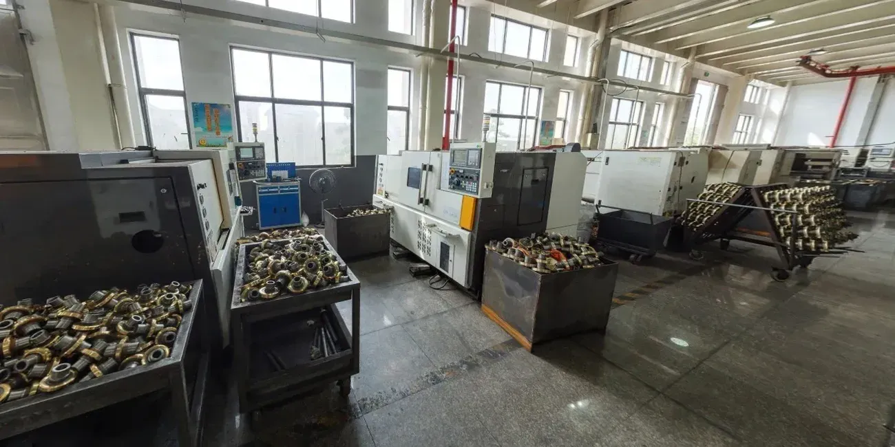
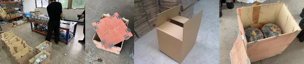
In the WP family model code, the WPDKA breaks down as follows: W = worm reducer family; P = box structure; D = motor-direct IEC flange input; K = hollow bore output; A = foot-mount base. The WPDKA is therefore the most interface-dense unit in the range — simultaneously providing: motor-direct input (no input coupling); hollow shaft output (no output coupling); and four-bolt foot-mount stability (stable machine base mounting). It represents the convergence of the WPDA (D = direct motor flange) and the WPKA (K = hollow output bore) in a single housing.
The practical result of this configuration density is a drivetrain that is two couplings shorter than a conventional arrangement. In a space-constrained machine — a common challenge in modern Australian automation and packaging equipment where ISO 80079 hazardous area requirements increasingly mandate compact enclosed drives — removing two couplings means removing two alignment interfaces, two coupling guards, two maintenance intervals, and two of the most common sources of drivetrain vibration and downtime. The WPDKA mounted on a machine base with a motor bolted to its input flange and a driven shaft through its output bore is fully operational with no more assembly than four input bolts, one bore key, and two or three setscrew turns.
The WPDKA housing is internally identical to the WPKA — same cast-iron housing, same worm shaft, same tin-bronze worm wheel, same rated output torques. The IEC flange is machined concentrically with the worm shaft axis to within 0.03 mm TIR, and the hollow output bore is finished to H7 tolerance per DIN 286. Together these two precision interfaces deliver the installation accuracy formerly achievable only through lengthy field alignment procedures.
Where WPDKA Sits in the WP Configuration Matrix
| Model | Input | Output | Couplings Eliminated | Best For |
|---|---|---|---|---|
| WPA / WPS | Coupling | Solid shaft | None | Standard foot-mount drives |
| WPDA / WPDS | IEC flange | Solid shaft | Input coupling only | Direct motor mount, solid shaft output |
| WPKA / WPKS | Coupling | Hollow bore | Output coupling only | Shaft-mount output, separate motor |
| WPDKA | IEC flange | Hollow bore | Input AND output couplings | Maximum compactness, zero coupling maintenance |
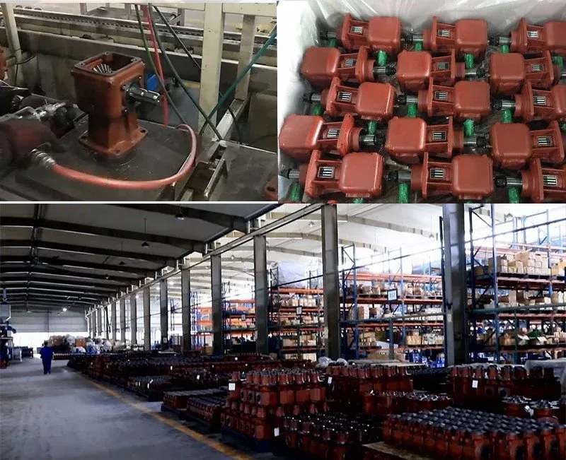
How to Select and Install the WPDKA — A Step-by-Step Guide
Selection:
- Define Both Interface Requirements Together: Unlike single-interface configurations (WPDA or WPKA), the WPDKA must satisfy both the motor flange and the bore requirements simultaneously. Start by confirming: (a) the IEC motor frame size (which constrains the minimum WPDKA frame size through the flange acceptance range); and (b) the driven shaft diameter (which must be ≤ the standard bore diameter for your chosen WPDKA frame). If these two constraints point to different frame sizes, select the larger of the two.
- Confirm IEC Flange Compatibility: WPDKA IEC flange acceptance ranges follow the same frame-to-reducer size pairings as the WPDA. Common pairings: WPDKA-60 → 63B5, 71B5; WPDKA-80 → 71B5, 80B5; WPDKA-100 → 90B5, 100B5; WPDKA-155 → 132B5, 160B5. Confirm your motor frame before ordering.
- Calculate Torque and Apply Service Factor: WPDKA rated output torques equal the WPKA (and WPA) at the same frame size. Apply SF 1.25–2.0 and select accordingly. For shock loads, consider whether the WPDKA (WPA-class housing) or a WPDKS equivalent (WPS-class housing with deeper bore) is more appropriate — contact Ever-Power’s engineering team for guidance.
- Verify Bore Engagement Length: Confirm that your driven shaft extends into the WPDKA bore by at least 1.2 × bore diameter. WPDKA bore depths (HL) are the same as WPKA — for higher engagement requirements, a custom WPDKS (WPS-class housing with deeper bore, IEC flange input) can be specified on enquiry.
Installation:
- Mount the Gearbox on the Driven Shaft First: Install the WPDKA onto the driven shaft (key-and-setscrew or shrink disc) before attaching the motor. With the gearbox on the shaft, mount the torque arm and connect it to the machine frame. Verify 3–5 mm free movement at the torque arm pivot before clamping.
- Mount the Motor to the IEC Flange: With the WPDKA in its final position, slide the motor shaft into the IEC B5 input flange and tighten the four motor flange bolts to DIN 912 specification. The IEC pilot bore self-centres the motor — no dial gauge alignment is required.
- Oil Fill: The WPDKA is dispatched without oil. With the unit in its installed orientation, fill to the sight glass centre with ISO VG 220 mineral oil before first run. The oil fill port location varies with mounting orientation — consult the supplied orientation diagram or contact Ever-Power for the specific port location for your mounting position.
- Run-In: Unloaded 30 minutes, 50% load 2 hours, then full load. Monitor housing surface temperature — target 40–70 °C above ambient in stabilised operation. If operating above 80 °C in Australian summer conditions (ambient 35–40 °C), switch to synthetic ISO VG 220 oil to improve thermal margin.
Accessories We Also Supply: Shrink disc assemblies for zero-clearance bore mounting, IEC adaptor rings for non-standard motor frames, torque arm kits with stainless steel option for food/washdown, motor support brackets for 100+ frame motors, DIN 6885 parallel keys, and output bore Viton seals. Contact Ever-Power Australia for pricing.
WPDKA Applications in Australian Compact Drive Design
The WPDKA is chosen by Australian OEM machine builders and plant engineers when maximum compactness and minimum coupling count are the primary engineering constraints:
- Packaging Machinery (Sydney, Melbourne): Label applicator roll drives, date-coder drives, and bottle-capper torque heads in Australian pharmaceutical and FMCG packaging lines where the motor must sit close to the driven roll with no external coupling. The WPDKA 60–80 with 63B5–80B5 brake motor is the standard specification for these compact motorised roll drives.
- Conveyor Shaft Drives (Brisbane, Sydney): Belt conveyor head shaft drives in confined conveyor tunnels or elevated-mezzanine installations in Australian distribution centres and food processing plants where the total drive envelope — from motor end to driven shaft — must fit within a fixed architectural opening. The WPDKA eliminates the motor base and both couplings that conventional drives require.
- Automated Assembly (Melbourne, Adelaide): Rotary table drives, pallet transfer shaft drives, and indexing mechanism shaft drives in Australian automotive assembly and pharmaceutical packing lines where servo motor direct-mount plus shaft-direct output provides the minimum backlash and maximum positional accuracy achievable with a worm reducer.
- Agricultural Equipment (QLD, NSW, SA): Seeder metering shaft drives, spreader impeller shaft drives, and boom pivot shaft drives on Australian cropping and livestock machinery where the WPDKA sits directly on the implement shaft with the motor flanged to the reducer — eliminating PTO gearbox intermediaries and simplifying maintenance for regional operators.
- Food Processing (Sydney, Brisbane, Melbourne): Mixing bowl shaft drives, ribbon blender shaft drives, and filling auger shaft drives in Australian food and beverage plants where the combination of IP65-rated flanged motor plus sealed WPDKA bore eliminates all external coupling surfaces that could harbour product residue — supporting compliance with Australian Standard AS/NZS 4696 for food machinery hygiene.
What Australian Customers Say About the DKA Series (WPDKA)
“We OEM the WPDKA 80 into our label applicator drives in Sydney. No coupling at either end — the motor flanges on, the applicator roll shaft goes in, done. Our assembly time per drive station dropped from 45 minutes to 12 minutes. No alignment tools required on the production line. This is the best OEM gearbox decision we’ve made.”
— Martin K., Design Director, Sydney NSW
“WPDKA 100 at 40:1 on our ribbon blender agitator shafts in Brisbane. The self-locking holds the blades in position when power is off — critical for our changeover safety procedure. The IEC servo motor flanges straight on. After 16 months of two-shift operation, the bore shows zero fretting and the input bearing is perfect.”
— Jenny W., Process Engineer, Brisbane QLD
“WPDKA 70 units on our automated packaging table shaft drives in Melbourne. Very compact, clean installation. The only reason for 4 stars is we needed a custom Ø28 mm bore for our table shaft — had to wait 2.5 weeks. For standard bore sizes the delivery was 8 days. Would recommend for any compact drive application.”
— Sarah B., Automation Engineer, Melbourne VIC
“Using WPDKA 120 units with 3 kW 112B5 motors for our filling auger drives in our Adelaide food plant. The food-grade oil pre-fill and Viton seals were easy to specify at order. Passed our food safety audit with no issues — no coupling surfaces to trap product. Ever-Power supply and after-sales support have been excellent.”
— Robert N., Production Manager, Adelaide SA
Why Choose Ever-Power for WPDKA Worm Reducers in Australia?
Ever-Power Worm Gear Reducer Co., Ltd. (Australia) at 27 Harley Crescent, Condell Park NSW 2200 stocks WPDKA units in common frame sizes and standard bore diameters for 5–10 business day dispatch. Non-standard bores and custom IEC flange sizes are available with 2–3 week lead time. Our engineering team confirms both the IEC flange and bore compatibility simultaneously — a free dual-interface check delivered within one business day. See our full capabilities at About Us and extended technical resources at worm-gearbox.top.