Description
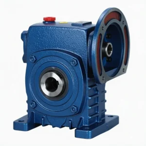
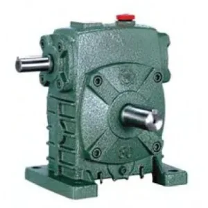
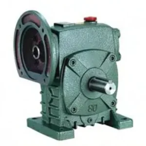
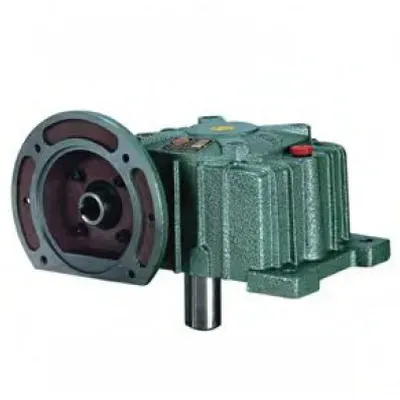
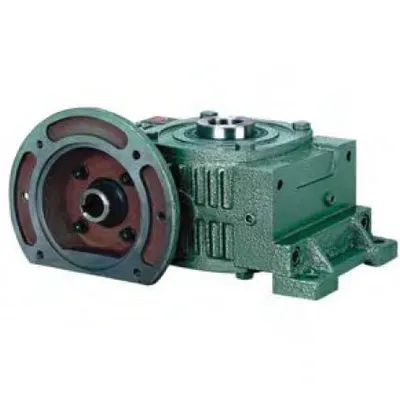
The WP worm gearbox family reaches its maximum functional density in the DX & DO Series (WPDX and WPDO) — the only configuration in the range that simultaneously integrates all three drive interface advantages: an IEC B5 motor-mounting flange at the input (no coupling, no alignment), and dual output shafts on the driven side. Where the WPDA offers direct motor mounting with single output, and the WPO/WPX offer dual output with shaft-coupled motor input, the WPDX and WPDO close the gap by delivering all three features in a single sealed right-angle housing. The WPDO provides two co-axial output shafts extending from opposite housing faces — mechanically guaranteeing identical speed on both simultaneously from a single flanged motor. The WPDX provides one co-axial output and a second output at 90° for offset-axis machine geometries. Covering sizes 50 through 155 with input powers from 0.18 kW to 5.5 kW and gear ratios from 10:1 to 60:1, the WPDX and WPDO serve Australian manufacturers in Sydney, Melbourne, Brisbane, Adelaide, and Perth who need the most compact possible motorised twin-drive arrangement. Manufactured to ISO 9001:2015, designed per AGMA 6034, supplied by Ever-Power Worm Gear Reducer Co., Ltd. (Australia), 27 Harley Crescent, Condell Park NSW 2200.
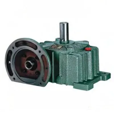
Key Specifications & Parameters — DX & DO Series (WPDX / WPDO)
WPDX — Motor Flange + 90° Dual Output
IEC B5 motor flange input. One co-axial output plus a second output at 90° via internal bevel stage. Ideal for L-shaped machine drive layouts requiring a flanged motor and offset-axis second output.
WPDO — Motor Flange + Co-Axial Dual Output
IEC B5 motor flange input. Twin co-axial output shafts on opposite housing faces — mechanically identical speed on both outputs at all times. For symmetrical twin-load machinery with direct motor mount.
| Size | Input Power (kW) | Ratio Range | Centre Dist. A (mm) | Overall Length B (mm) | Output Shaft LS (mm) | Output Shaft S (mm) | IEC Flange LA (mm) | Weight (kg) |
|---|---|---|---|---|---|---|---|---|
| 50 | 0.18 | 10:1 – 60:1 | 165 | 145 | 40 | 40 | 115 | 7 |
| 60 | 0.37 | 10:1 – 60:1 | 185 | 165 | 50 | 50 | 130 | 10 |
| 70 | 0.55 | 10:1 – 60:1 | 215 | 195 | 60 | 65 | 145 | 15 |
| 80 | 0.75 | 10:1 – 60:1 | 250 | 210 | 65 | 85 | 160 | 23 |
| 100 | 1.5 | 10:1 – 60:1 | 310 | 245 | 75 | 85 | 165 | 36 |
| 120 | 3.0 | 10:1 – 60:1 | 370 | 285 | 85 | 100 | 200 | 63 |
| 135 | 4.0 | 10:1 – 60:1 | 415 | 320 | 95 | 110 | 225 | 83 |
| 155 | 5.5 | 10:1 – 60:1 | 442 | 392 | 110 | 140 | 265 | 120 |
What Are the WPDX and WPDO — and Where Do They Fit in the WP Family?
To place the WPDX and WPDO in context, consider the WP family as a matrix of input and output options. The WPO/WPX provides dual output but requires a shaft-coupled motor input. The WPDA provides IEC motor flange input but only a single output. The WPDX and WPDO close the remaining quadrant — providing both IEC motor flange input AND dual output — in the most compact possible form factor.
| WP Configuration | Input Type | Output Count | Output Geometry |
|---|---|---|---|
| WPA / WPS | Shaft coupling | Single | Solid shaft, single side |
| WPDA / WPDS | IEC B5 motor flange | Single | Solid shaft, single side |
| WPO / WPX | Shaft coupling | Dual | Co-axial (WPO) or 90° (WPX) |
| WPDO / WPDX | IEC B5 motor flange | Dual | Co-axial (WPDO) or 90° (WPDX) |
The WPDO and WPDX are manufactured on the same housing castings as the WPO and WPX respectively — with the IEC B5 input flange machined into the same face that accommodates the shaft input in the WPO/WPX. The result is a gear centre that is identical internally (same worm shaft, same bronze wheel, same bearing arrangement), with external interfaces upgraded to eliminate both the motor coupling and the output coupling. This three-point coupling elimination — motor input, and both output shafts if hollow-bore options are specified — can reduce total machine coupling count from up to five separate flexible elements to zero.

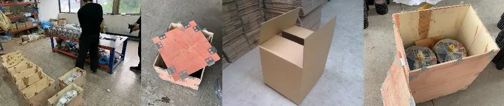
How to Select WPDX or WPDO — Decision Guide for Australian Engineers
- Define Machine Geometry: If both driven loads are co-axial (same axis, extending from opposite sides of the machine symmetrically), specify WPDO. If the second driven load exits at 90° to the first (L-shaped drive layout, or second load on a perpendicular shaft), specify WPDX.
- Confirm Motor Frame: Select the IEC motor frame based on required input power. Cross-reference against the WPDX/WPDO IEC flange acceptance range for your chosen frame size. The same IEC flange compatibility as the WPDA applies — refer to the IEC frame-to-reducer size matching table from the WPDA section for guidance.
- Calculate Total Torque: The WPDO/WPDX rated output torque is the total available across both output shafts. Sum both output load torques (with service factors applied) and confirm this does not exceed the WPDO frame’s rated output torque. For unequal load applications, also check that the heavier-loaded shaft is not subjected to more than 70% of the total rated torque alone — if it is, use a torque-limiting coupling on the lighter-loaded stub.
- Check Self-Locking: At ratios 20:1 and above, the worm stage is self-locking. For WPDX, the bevel stage at the 90° output is not self-locking — if that load is gravity-loaded, a separate brake on the 90° output shaft is required per AS 4024.
- Consider Thermal Rating: The motor heat is transferred to the WPDO/WPDX housing via the IEC flange face. In ambient temperatures above 35 °C (common in QLD, WA, NT), confirm the thermal rated power at your local ambient. Specify synthetic ISO VG 220 oil if thermal margin is below 15%.
Accessories We Also Supply: Motor support brackets (for 100+ frame IEC motors), finished-bore sprockets for both output stubs, IEC adaptor rings for non-standard motor frames, torque-limiting couplings for unbalanced load protection, output shaft seals (NBR and Viton). Contact Ever-Power Australia for a combined supply quote.
WPDX / WPDO Applications in Australian Industrial Machinery
The WPDX and WPDO series are found across Australian industrial sectors wherever compact motor-direct twin-load drive is needed — eliminating separate motor bases, couplings, and cable lengths that would otherwise be required for two independently driven loads:
| Industry & Location | Application | Model | Key Advantage |
|---|---|---|---|
| Packaging (Sydney, Melbourne) | Twin infeed/outfeed conveyor from single motor | WPDO | Mechanical sync + motor-direct = most compact possible drive |
| Dyeing/Textile (Melbourne, Geelong) | Balanced fabric spreader rolls with direct motor | WPDO | No coupling on motor or either output roll |
| Pharmaceutical (Sydney, Melbourne) | Tablet press dual-feed scraper drives | WPDO | Clean-room compatible — no external coupling surfaces |
| Agricultural Machinery (QLD, NSW) | Dual-auger fertiliser spreader | WPDX | Motor offset from spreader centreline, 90° output matches auger geometry |
| Material Handling (Brisbane, Perth) | Bridge crane symmetrical end-carriage travel | WPDO | Motor-direct flanged unit + identical wheel speed — minimum machine complexity |
Case Study: Replacing Three-Component Drive Train with Single WPDO Unit
A Sydney pharmaceutical packaging OEM contacted Ever-Power with a machine redesign challenge: their tablet inspection conveyor used two separate 0.75 kW motors, each with its own coupling, gearbox, and motor base, driving the infeed and outfeed belts of an inspection carousel. The twin-motor arrangement required electronic speed synchronisation via a VFD master-slave configuration — a source of periodic calibration downtime and a potential single-point-of-failure for the production line.
Ever-Power’s engineering team proposed replacing both drives with a single WPDO 80 at 30:1 with an 80B5 0.75 kW brake motor mounted directly on the IEC flange. The result: both conveyor belts now run at mechanically identical speed from a single motor, eliminating the VFD synchronisation loop entirely. Total component count dropped from 10 items (2 motors + 2 VFDs + 2 couplings + 2 gearboxes + 2 motor bases) to 3 items (1 brake motor + 1 WPDO + 2 sprockets). Machine noise dropped by an estimated 8 dB(A) at the inspection station due to the elimination of two coupling guards and motor bases.
What Australian Customers Say About the DX & DO Series
“The WPDO 80 at 30:1 with a direct-flanged brake motor on our Sydney conveyor redesign eliminated 7 components. Our maintenance team is genuinely impressed — one oil change per gearbox, one motor to manage, and zero calibration required on the speed sync. Best machine simplification we’ve done in years.”
— Daniel F., OEM Design Manager, Sydney NSW
“WPDX 100 at 20:1 on our Melbourne dual-auger fertiliser spreader. The 90° output was essential — the motor sits on the WPDX flange at the machine centreline and the two augers exit at right angles on either side. Clean layout, no couplings to maintain. 16 months running without a stop.”
— Gavin S., Agricultural Machinery Engineer, Melbourne VIC
“Fitted WPDO 60 units to our Brisbane dyeing range spreader rolls with direct-flanged 63B5 servo motors. Fabric tracking is perfect — the mechanical synchronisation eliminates the speed correction we used to have to dial in after every product changeover. Not 5 stars only because we needed a 3-week lead time for the servo-compatible low-backlash variant.”
— Angela T., Production Engineer, Brisbane QLD
“We specify WPDO units for our bridge crane end-carriage travel drives in WA. The combination of motor-direct input and mechanical synchronisation of both wheels makes commissioning trivial — bolt on the motor, bolt on the sprockets, and go. No electronic synchronisation setup required at all. Ever-Power supply is reliable and competitive.”
— Peter N., Crane Design Engineer, Perth WA
Why Choose Ever-Power for WPDX / WPDO Worm Gear Reducers in Australia?
Ever-Power Worm Gear Reducer Co., Ltd. (Australia) at 27 Harley Crescent, Condell Park NSW 2200 maintains stock of WPDO and WPDX units in common frame sizes and ratios for 5–10 business day dispatch. Our engineering team provides free dual-load calculation analysis, IEC flange compatibility checks, and WPDX vs WPDO configuration guidance — all within one business day. Read about our full capabilities at About Us and explore additional technical resources at worm-gearbox.top.