Description
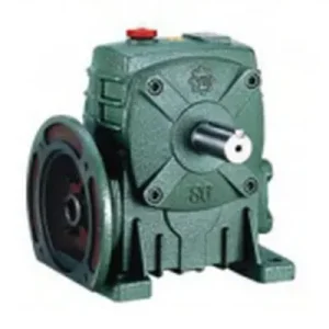
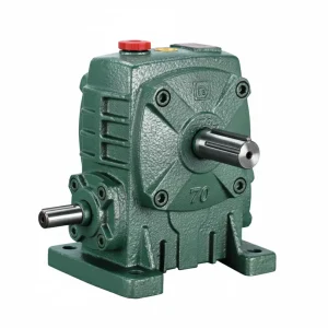
The fastest way to eliminate output-side coupling failures in an industrial worm drive is to remove the coupling entirely — and the KA Series (WPKA) hollow bore worm gear reducer does exactly that. Where the standard WPA presents a solid output shaft stub that requires a separate coupling to connect to the driven machine, the WPKA output passes straight through the worm wheel hub as a precision-bored hollow shaft, accepting the driven machine shaft directly. The driven shaft slides into the bore, engages via a standard DIN 6885 key and setscrew, and the WPKA sits directly on the machine — no coupling, no coupling guard, no alignment shims, no intermediate bearing housing. The axial length saved at the output side is typically 80–150 mm depending on frame size, and the eliminated coupling represents one of the top three sources of planned maintenance downtime in shaft-drive worm gearbox installations across Australian manufacturing facilities in Sydney, Melbourne, Brisbane, and Perth. Covering centre distances from size 50 to 200, bore diameters from Ø20 mm to Ø80 mm, and gear ratios from 10:1 to 60:1, the WPKA is specified across packaging, food processing, material handling, and agricultural machinery throughout Australia. Manufactured to ISO 9001:2015, designed per AGMA 6034, and supplied by Ever-Power Worm Gear Reducer Co., Ltd. (Australia), 27 Harley Crescent, Condell Park NSW 2200.
Key Specifications & Parameters — KA Series (WPKA) Hollow Bore Worm Gear Reducer
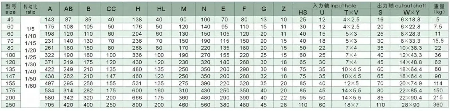
All parameters per ISO 9001:2015, AGMA 6034, and DIN 3975 gear quality specification. Bore tolerances to H7 per DIN 286.
| Size | Ratio Range | Centre Dist. A (mm) | Hub Width AB (mm) | Overall Length B (mm) | Height H (mm) | Bore Length HL (mm) | Output Bore Ø (mm) | Weight (kg) |
|---|---|---|---|---|---|---|---|---|
| 50 | 10:1–60:1 | 175 | 105 | 107 | 180 | 50 | Ø20 | 7 |
| 60 | 10:1–60:1 | 195 | 120 | 117 | 210 | 60 | Ø25 | 10.5 |
| 70 | 10:1–60:1 | 234 | 140 | 131 | 243 | 70 | Ø30 | 14.5 |
| 80 | 10:1–60:1 | 264 | 160 | 144 | 273 | 80 | Ø35 | 22 |
| 100 | 10:1–60:1 | 322 | 190 | 175 | 340 | 100 | Ø40 | 36 |
| 120 | 10:1–60:1 | 385 | 230 | 200 | 405 | 120 | Ø45 | 63 |
| 135 | 10:1–60:1 | 435 | 260 | 212 | 455 | 135 | Ø60 | 80 |
| 155 | 10:1–60:1 | 507 | 302 | 312 | 490 | 135 | Ø70 | 114 |
What Is the WPKA Series and How Does the Hollow Bore Work?
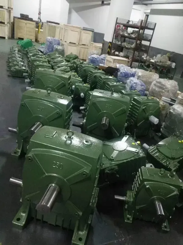
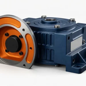
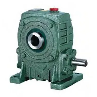
In the WP family model code, K denotes the hollow output shaft configuration. The WPKA is therefore a K-output (hollow bore), A-base (foot-mount) worm reducer — maintaining the same cast-iron housing and four-bolt foot-mount base as the WPA, while replacing the solid output shaft stub with a through-bore machined to H7 tolerance through the centre of the worm wheel hub.
The hollow bore engagement works as follows: the driven machine shaft is inserted into the WPKA output bore until the keyway slots align. A standard DIN 6885 parallel key is inserted, and a locking setscrew in the bore hub clamps the assembly. A torque arm bracket — supplied with each WPKA — is then bolted to the housing face and pin-connects to the machine frame, reacting the rotational moment of the housing without requiring any additional mounting feet or base plates. This torque-arm arrangement is the standard shaft-mount configuration used across Australian screw conveyor drives, mixer shaft drives, and grain auger applications where mounting a gearbox base plate is either impractical or impossible due to machine geometry.
The WPKA inherits the WPA housing geometry — meaning its rated output torque and thermal power at each frame size and ratio are identical to the WPA. The hollow bore replaces only the output shaft stub; the worm wheel, worm shaft, bearings, and sealing are unchanged. The critical distinction between the WPKA and the WPKS (its heavy-duty hollow-bore counterpart) is the bore length (HL): WPKA bore depths range from 50 mm (size 50) to 135 mm (size 155), compared with 130–390 mm for the WPKS — the WPKA is the standard-duty hollow bore unit, appropriate for shaft engagement lengths within the WPA torque rating; the WPKS is specified for heavy-load, long-bore-engagement applications.
WPKA vs WPA vs WPKS — Which Hollow-Shaft Specification Is Right for You?
| Feature | WPA (solid shaft) | WPKA (standard hollow bore) | WPKS (heavy hollow bore) |
|---|---|---|---|
| Output connection | Coupling to driven shaft | Direct bore onto driven shaft | Direct bore, longer engagement |
| Bore depth HL (size 100) | N/A (solid shaft) | 100 mm | 250 mm (+150%) |
| Axial footprint saving | None | 80–120 mm vs coupling | 80–120 mm vs coupling |
| Shock load tolerance | Standard (coupling absorbs) | Standard — WPA-class housing | Higher — WPS-class bearing |
| Best for | Any motor shaft via coupling | Light–medium shaft loads | Heavy shock, long shaft engagement |
| Torque arm required | No | Yes (included) | Yes (included) |
Manufacturing Quality: Bore Precision and Material Specification
The hollow output bore is the most dimensionally critical feature of the WPKA, as any bore-to-shaft clearance or angular misalignment directly transfers as torsional shock to the worm wheel hub. The following manufacturing controls ensure bore integrity:
- Bore Tolerance H7 per DIN 286: The output bore is finished to H7 tolerance — for a Ø40 mm bore (size 100), this means +0 to +0.025 mm over nominal. This provides a clearance fit of approximately 0.010–0.045 mm onto an h6-tolerance driven shaft, ensuring full key engagement without fretting between bore and shaft.
- Single-Setup Boring: The bore is finish-machined in the same CNC fixture setup as the housing bearing bores, ensuring the output bore axis is parallel to the worm wheel shaft axis within 0.02 mm/100 mm. Axial misalignment above this level would cause uneven keyway contact under torque and premature bore wear.
- Keyway Dimensions per DIN 6885: Keyway width, depth, and length tolerance follow DIN 6885 Part 1 (Form A parallel key) standards. This ensures that standard Australian-market parallel keys sourced locally will fit correctly without re-machining.
- Worm Wheel Material (ZCuSn10Pb1): The tin-bronze worm wheel through which the bore passes is produced from a single-piece casting with no internal joints or welds, ensuring full structural integrity of the hub wall surrounding the bore even when the bore is at maximum diameter relative to the hub OD.
- Housing: GG25 Cast Iron: The same cast-iron housing specification as the WPA provides the structural rigidity to resist the bending moment from the torque arm reaction force without housing distortion at rated load.
How to Select and Install the WPKA Hollow Bore Worm Reducer
Selection:
- Confirm Driven Shaft Diameter: The bore diameter must match your driven machine shaft. Standard WPKA bore diameters are Ø20–Ø70 mm as listed in the spec table. Non-standard bore diameters (e.g., Ø38 or Ø42 mm) are available as factory custom options with a 2–3 week lead time — specify at time of order.
- Calculate Required Torque and Select Frame Size: WPKA rated output torques are identical to the WPA at the same frame size. Apply service factor (SF 1.25–2.0) to your design torque and select accordingly. For continuous shock loading (e.g., grain auger starting under full load), consider upgrading to WPKS at the same frame size for its deeper bore engagement and heavier bearing arrangement.
- Confirm Bore Length Coverage: Verify that your driven shaft’s engagement length into the bore (the length of shaft inside the WPKA hub) is at least 1.2 × the bore diameter — the minimum engagement length for reliable key torque transfer per DIN 6885 recommendations. For Ø40 mm bore (size 100, HL=100 mm), the minimum engagement is 48 mm. If your shaft does not extend sufficiently into the bore, specify the WPKS for its longer bore depth.
- Size the Torque Arm: The maximum output torque multiplied by the housing-to-torque-arm-pivot distance gives the torque arm pin load. Ensure the machine frame can accommodate the torque arm pin load in shear at the pin attachment point.
Installation:
- Shaft Preparation: Clean the driven shaft of any burrs, paint, or surface rust in the engagement zone. Apply a thin film of anti-fretting compound (e.g., Molykote G-n or equivalent) to the shaft surface before sliding the WPKA onto the shaft.
- Key Insertion: Insert the DIN 6885 parallel key into the shaft keyway first, then slide the WPKA bore over the shaft and key simultaneously. Never force the WPKA with a hammer — if resistance is felt, check for keyway misalignment or a burr on the key edges.
- Setscrew Torquing: Tighten the bore hub setscrew(s) to the specified torque — typically 10 N·m (M8 setscrew) to 25 N·m (M12 setscrew) depending on frame size. Torquing to specification is critical: undertorqued setscrews allow axial slip of the reducer on the shaft under cyclic loads; overtorqued setscrews can crack the hub wall on smaller frame sizes.
- Torque Arm Installation: Mount the torque arm bracket to the housing using the supplied M10 or M12 bolts torqued to DIN 912 specification. Connect the free end to the machine frame via the rubber-bushed pivot pin supplied. Confirm 3–5 mm of free movement at the pivot before clamping — this prevents binding under thermal expansion of the machine shaft during operation.
Accessories We Also Supply: Torque arm replacement rubber bushes, DIN 6885 parallel keys (standard and oversized), anti-fretting compound (Molykote G-n), shaft locking assemblies (shrink disc option for zero-clearance mounting), replacement oil seals (NBR and Viton), and IEC motor adaptor flanges for input side. Contact Ever-Power Australia for pricing.
Applications of the WPKA Hollow Bore Worm Reducer Across Australia
The WPKA’s shaft-direct mounting is particularly valued in Australian industrial and agricultural applications where the driven shaft is exposed and accessible but the machine frame cannot accommodate a conventional foot-mount gearbox base:
| Sector & Location | Application | WPKA Size / Ratio |
|---|---|---|
| Grain Handling (QLD, NSW, SA) | Screw auger shaft drives, grain conveyor head shaft | Size 80–120, 20:1–40:1 |
| Mixing (Sydney, Melbourne) | Agitator shaft drives, ribbon-blender shaft mounts | Size 70–100, 30:1–60:1 |
| Packaging (Sydney, Melbourne) | Conveyor roller shaft drives, turntable shaft mounts | Size 50–80, 20:1–40:1 |
| Water Treatment (Perth, Adelaide) | Sludge scraper shaft drives, filter-press shaft mounts | Size 100–135, 40:1–60:1 |
| Agricultural Machinery (WA, VIC) | Irrigation boom pivot shaft, seeder metering shaft | Size 60–80, 30:1–60:1 |
What Australian Customers Say About the WPKA Series
“Replaced three WPA units on our Sydney conveyor line with WPKA 80s. The hollow shaft mounts directly on the conveyor head shaft — we went from three coupling alignments per year to zero maintenance on those drive connections. The 80–100 mm saved on each conveyor section was genuinely useful for our layout redesign.”
— Alex P., Mechanical Engineer, Sydney NSW
“WPKA 100 at 40:1 on our grain auger head shaft in Queensland. The torque arm bolts straight to the machine frame and the WPKA sits directly on the auger shaft — no separate bearing, no coupling. Clean install, runs quietly. Second order placed after 14 months of trouble-free operation.”
— Tim W., Grain Handler, Darling Downs QLD
“WPKA 70 units on our ribbon blender agitator shafts in Melbourne. Self-locking at 30:1 means the blades stay put when power is off — no drift. Would be 5 stars but one bore needed minor cleaning of a burr before the key would seat fully. Easy to fix but worth noting for incoming inspection.”
— Rachel T., Maintenance Engineer, Melbourne VIC
“We fit WPKA 60 units to our irrigation boom pivot shafts in WA. The hollow shaft directly on the pivot shaft is far simpler than the old coupling-and-bracket arrangement we ran for years. With self-locking at 60:1 the boom stays exactly where we leave it. Ever-Power supply is reliable and pricing is excellent.”
— Don M., Irrigation Manager, Geraldton WA
Why Choose Ever-Power for WPKA Hollow Bore Worm Reducers in Australia?
Ever-Power Worm Gear Reducer Co., Ltd. (Australia) at 27 Harley Crescent, Condell Park NSW 2200 stocks WPKA units across all eight frame sizes in standard bore diameters for 5–10 business day dispatch. Custom bore diameters are available in 2–3 weeks. Our engineering team provides free bore engagement confirmation and torque arm sizing for your specific shaft arrangement. Learn more at About Us. Technical reference at worm-gearbox.top.