Description
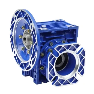
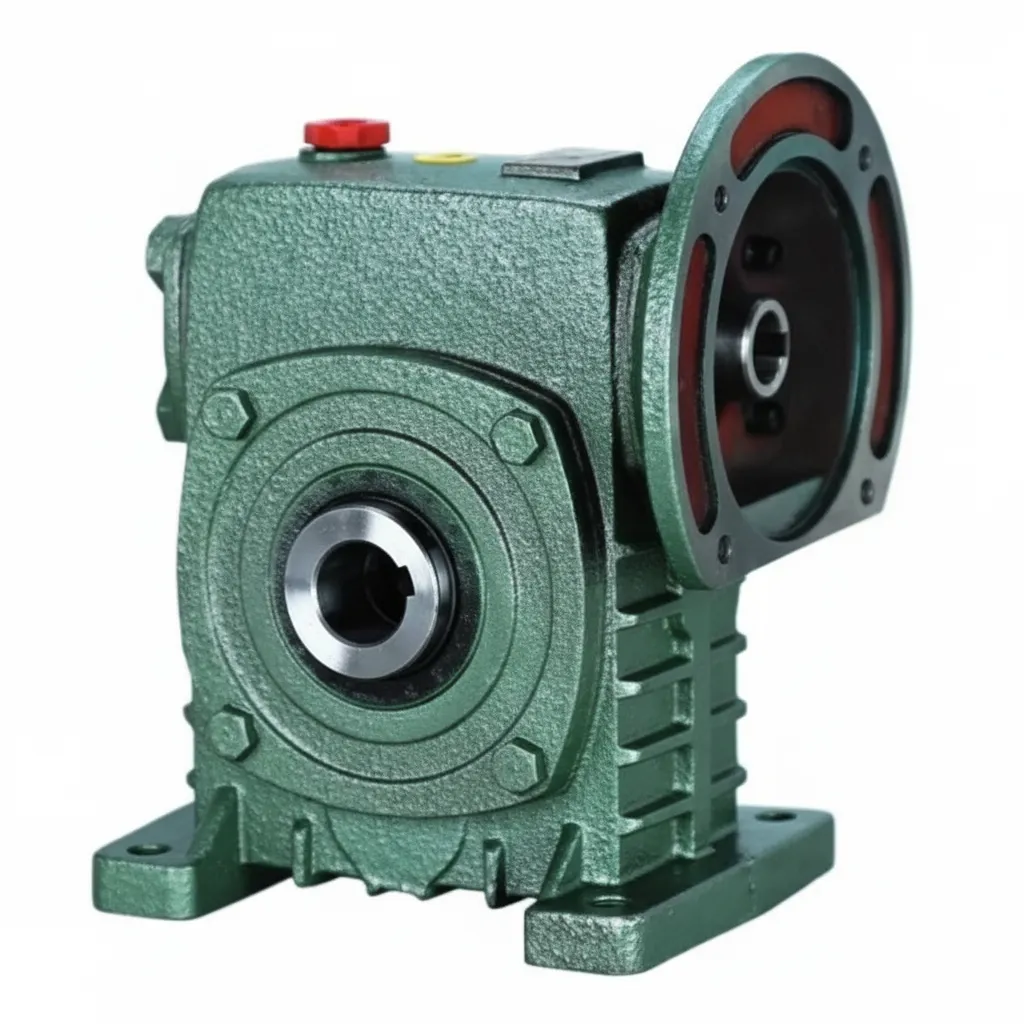
The WDK Series worm gear reducer closes the one gap the W family previously left open: a genuinely zero-coupling hollow-bore unit within the W-series dimensional convention, where the IEC B5 motor flange on the input face completely replaces the through-shaft — not as an addition to it — and the hollow bore output seats directly onto the driven shaft with no output coupling required. Where the FCWK retains a shaft extension on the non-flange input side (providing secondary access for an encoder or hand-wheel), the WDK eliminates that shaft entirely: the housing input face is a clean IEC flange, the output face is a clean hollow bore, and there are no external rotating shaft elements anywhere on the unit except where they interface with the driven machine. For Australian plant engineers in Sydney, Melbourne, Brisbane, Perth, and Adelaide who operate W-convention machinery and need the maximum coupling elimination — without the through-shaft configuration of the FCWK — the WDK is the correct specification. Covering sizes 50–155, input powers 0.18–5.5 kW, bore diameters Ø20–Ø70 mm, and ratios 10:1–60:1. Manufactured to ISO 9001:2015, designed per AGMA 6034, and supplied by Ever-Power Worm Gear Reducer Co., Ltd. (Australia), 27 Harley Crescent, Condell Park NSW 2200.
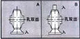
Technical Specifications — WDK Series Worm Gear Reducer
All parameters per ISO 9001:2015, AGMA 6034, and IEC 60034-7. Bore H7/DIN 286. IEC B5 flange machined concentric with worm shaft to 0.03 mm TIR.
| Size | Power (kW) | Ratio | A (mm) | B (mm) | H (mm) | HL (mm) | Flange LZ (mm) | Input Pilot Ø Q (mm) | Bore Ø S (mm) | Weight (kg) |
|---|---|---|---|---|---|---|---|---|---|---|
| 50 | 0.18 | 10:1–60:1 | 165 | 107 | 150 | 35 | 140 | 25 | Ø20 | 7 |
| 60 | 0.37 | 10:1–60:1 | 185 | 117 | 177 | 42 | 160 | 35 | Ø25 | 11 |
| 70 | 0.37–0.75 | 10:1–60:1 | 209 | 131 | 215 | 55 | 160–200 | 35–45 | Ø30 | 14 |
| 80 | 0.75–1.5 | 10:1–60:1 | 242 | 144 | 250 | 65 | 200 | 45 | Ø35 | 22 |
| 100 | 1.5 | 10:1–60:1 | 310 | 175 | 310 | 80 | 200 | 55 | Ø40 | 36 |
| 120 | 2.2–3.0 | 10:1–60:1 | 361 | 200 | 370 | 95 | 250 | 65 | Ø45 | 63 |
| 135 | 3.0–4.0 | 10:1–60:1 | 412 | 212 | 425 | 105 | 250 | 65 | Ø60 | 80 |
| 155 | 5.5 | 10:1–60:1 | 442 | 312 | 461 | 103 | 300 | 85 | Ø70 | 114 |
What Makes the WDK Different from FCWK and WPDKA?
| Feature | FCWK (W family) | WDK (W family) | WPDKA (WP family) |
|---|---|---|---|
| Input | IEC flange + secondary shaft stub | IEC flange only — no shaft extension | IEC flange only |
| Output | Hollow bore (W-class) | Hollow bore (W-class) | Hollow bore (WP-class bore Ø) |
| Secondary input access | Yes — encoder/hand-wheel possible | No — cleanest housing envelope | No |
| Bore Ø (size 100) | Ø40 mm (W-class) | Ø40 mm (W-class) | Ø40 mm (WP-class) |
| Dimensional convention | W series | W series | WP/IEC series |
| Choose when | Need IEC flange + encoder/hand-wheel access | Need cleanest zero-coupling W-convention unit | WP/IEC convention, IEC flange + hollow bore |
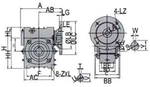

How to Select the WDK — Step-by-Step Guide
- Confirm W-convention bore requirement: WDK bore diameters (Ø20–Ø70 mm) follow the W series convention — the same bore diameters as the WA/WS at equivalent frame sizes. If your driven shaft is sized to a W-convention bore, specify WDK. If your shaft is sized to a WP-convention bore (e.g., Ø40 mm at size 100), which matches the WPDKA, also check — at size 100 the bore diameters are the same (both Ø40 mm). Confirm by measuring your existing bore before ordering.
- Confirm IEC motor frame: The WDK input flange (LZ dimension) accepts standard IEC B5 motor frames. Typical pairings: WDK-60 → 63B5; WDK-80 → 71B5, 80B5; WDK-100 → 90B5; WDK-120/135 → 112B5; WDK-155 → 132B5. Provide your motor’s IEC frame designation to Ever-Power for confirmed compatibility.
- Calculate torque and frame size: WDK rated output torques follow the W-series convention at each frame size. Apply service factor (SF 1.25–2.0) and select accordingly.
- Check bore engagement: Confirm shaft engagement length ≥ 1.2 × bore Ø (minimum per DIN 6885). WDK bore depths (HL) are comparable to WA-class at each frame. For shock loads requiring deeper engagement, enquire about a WDKS variant (WDK + WS-class deep bore) — contact Ever-Power for availability.
- Installation sequence: Mount WDK on driven shaft first (bore engagement), then connect torque arm to machine frame, then bolt IEC motor to input flange. Oil fill before first start.
Accessories We Also Supply: W-family torque arm kits (WDK-specific), shrink disc assemblies (Ø35+ bores), motor support brackets (frame 100+), IEC adaptor rings for non-standard motor frames, and DIN 6885 parallel keys. Contact Ever-Power Australia.
WDK Applications in Australian W-Convention Machinery
- Legacy machine IEC motor upgrades (all states): W-convention machinery that previously used WA or WS with coupled motors can be upgraded to WDK when IEC motor direct mount is desired — the WDK’s W-series bore dimensions match the existing driven shaft, and the IEC flange replaces the coupling at the motor side.
- Compact packaging and conveyor drives (Sydney, Melbourne): WDK at sizes 60–80 for W-convention conveyor and packaging line shaft drives where the cleanest possible installation is required — no coupling housing, no coupling guard, no shaft extension on the motor side of the housing.
- Food processing mixer shaft drives (Brisbane, Adelaide): WDK at sizes 80–120 on agitator and ribbon-blender shaft drives in W-convention food machinery where IP65 IEC motors must mount directly and the hollow bore output passes directly over the agitator shaft — zero external coupling surfaces for AS/NZS 4696 food safety compliance.
- Agricultural shaft drives (QLD, NSW, SA): WDK at sizes 70–100 on W-convention implement drives where compact drive geometry and IEC motor compatibility are both required and through-shaft secondary access is not needed.
What Australian Customers Say About the WDK Series
“WDK 100 replaced WA 100 units in our Sydney food plant — matched the W-convention bore dimensions exactly and eliminated the input coupling. Motor swap went from 2 hours to 20 minutes. The clean housing with no shaft extension on the back is exactly what we needed for the tight machine envelope.”
— Lisa P., Engineering Manager, Sydney NSW
“WDK 80 on our Brisbane packaging conveyor shaft drives. IEC 80B5 brake motor flanges straight on, conveyor shaft into the Ø35 bore. Zero external couplings in our W-convention machine. IP65 motor plus WDK passes our food safety audit. 18 months without issues.”
— Nathan B., Production Engineer, Brisbane QLD
“WDK 120 for our Melbourne W-convention grain conveyor upgrade — needed IEC motor direct mount and the W-convention Ø45 bore. Clean, compact installation. 4 stars only because I needed the WDKS variant (deeper bore) which required a 3-week lead time. Standard WDK bore depth was fine for this application though.”
— James C., Conveyor Engineer, Melbourne VIC
“WDK 135 at 40:1 on our SA grain auger drive. IEC 112B5 motor flanges straight on, Ø60 W-convention bore over the auger shaft. The WDK matched our W-family housing dimensions perfectly — no machine modification. Ever-Power’s technical team confirmed the bore compatibility before we committed. Excellent support.”
— Bruce P., Agricultural Engineer, SA Riverland
Why Choose Ever-Power for WDK Worm Reducers in Australia?
Ever-Power Worm Gear Reducer Co., Ltd. (Australia) at 27 Harley Crescent, Condell Park NSW 2200 stocks WDK units across common frame sizes for 5–10 business day dispatch. We confirm IEC flange compatibility and W-convention bore diameter match in one written recommendation. Visit About Us and worm-gearbox.top.